Chapter V STRUCTURAL DAMAGE FROM AIR BLAST
INTRODUCTION
GENERAL OBSERVATIONS
5.01 The two preceding chapters have dealt with general principles of air blast and the loads on structures produced by the action of the air blast wave. In the present chapter, the actual damage to buildings of various types, bridges, utilities, and vehicles caused by nuclear explosions will be considered. In addition, criteria of damage to various targets will be discussed and quantitative relationships will be given between the damage and the distances over which such damage may be expected from nuclear weapons of different yields.
5.02 Direct damage to structures attributable to air blast can take various forms. For example, the blast may deflect structural steel frames, collapse roofs, dish-in walls, shatter panels, and break windows. In general, the damage results from some type of displacement (or distortion) and the manner in which such displacement can arise as the result of a nuclear explosion will be examined.
5.03 Attention may be called to an important difference between the blast effects of a nuclear weapon and those due to a conventional high-explosive bomb. In the former case, the combination of high peak overpressure, high wind (or dynamic) pressure, and longer duration of the positive (compression) phase of the blast wave results in “mass distortion” of buildings, similar to that produced by earthquakes and hurricanes. An ordinary explosion will usually damage only part of a large structure, but the blast from a nuclear weapon can surround and destroy whole buildings in addition to causing localized structural damage.
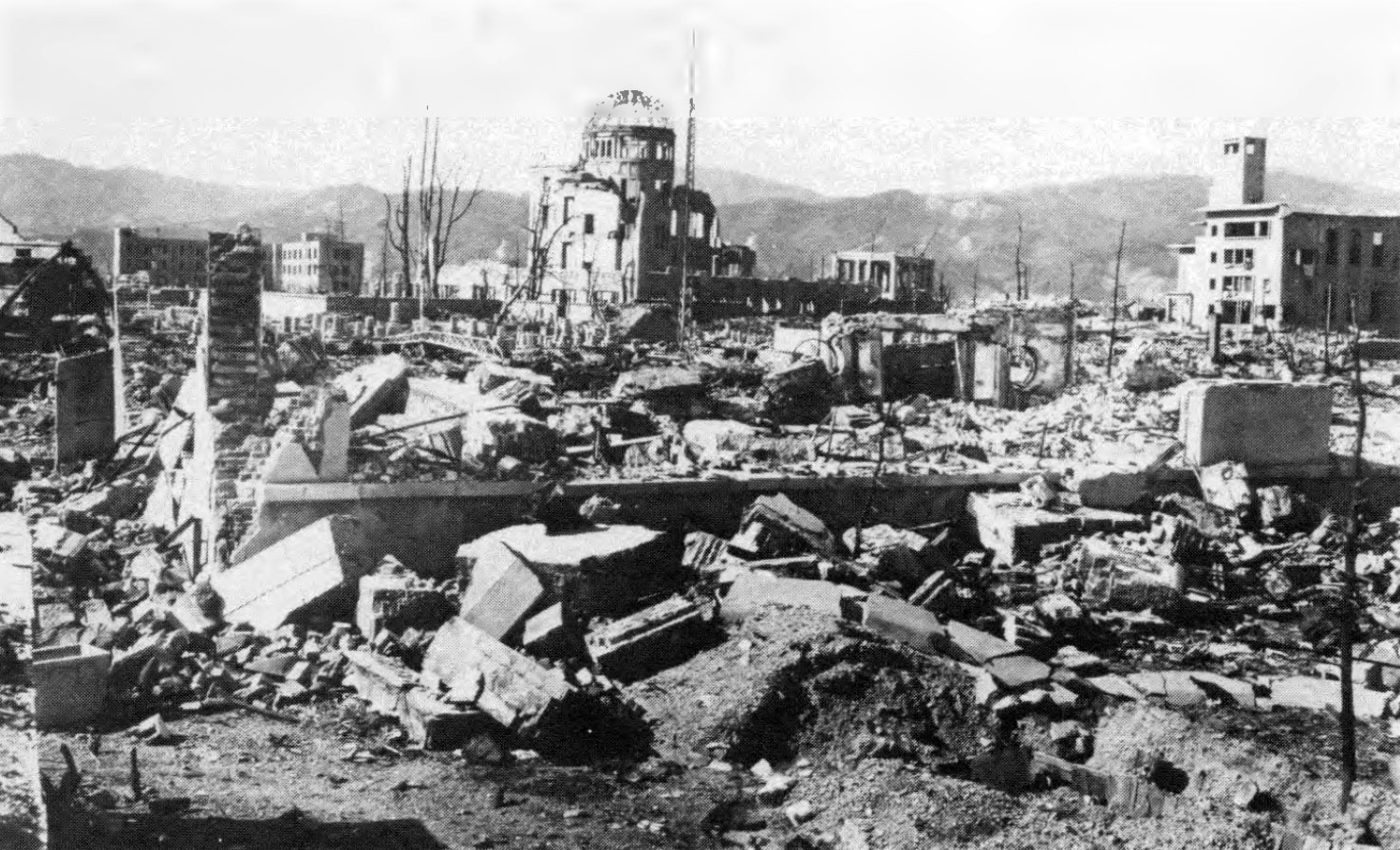
5.04 An examination of the areas in Japan affected by nuclear explosions (§ 2.24) shows that small masonry buildings were engulfed by the oncoming pressure wave and collapsed completely. Light structures and residences were totally demolished by blast and subsequently destroyed by fire. Industrial buildings of steel construction were denuded of roofing and siding, and only twisted frames remained. Nearly everything at close range, except structures and smokestacks of strong reinforced concrete, was destroyed. Some buildings leaned away from ground zero as though struck by a wind of stupendous proportions. Telephone poles were snapped off at ground level, as in a hurricane, carrying the wires down with them. Large gas holders were ruptured and collapsed by the crushing action of the blast wave.
5.05 Many buildings, which at a distance appeared to be sound, were found on close inspection to be damaged and gutted by fire. This was frequently an indirect result of blast action. In some instances the thermal radiation may have been responsible for the initiation of fires, but in many other cases fires were started by overturned stoves and furnaces and by the rupture of gas lines. The loss of water pressure by the breaking of pipes, mainly due to the collapse of buildings, and other circumstances arising from the explosions, contributed greatly to the additional destruction by fire (Chapter VII).
5.06 A highly important consequence of the tremendous power of the nuclear explosions was the formation of enormous numbers of flying missiles consisting of bricks (and other masonry), glass, pieces of wood and metal, etc. These caused considerable amounts of secondary damage to structures and utilities, and numerous casualties even in the lightly damaged areas. In addition, the large quantities of debris resulted in the blockage of streets, thus making rescue and fire-fighting operations extremely difficult (Fig. 5.06).
5.07 Many structures in Japan were designed to be earthquake resistant, which probably made them stronger than most of their counterparts in the United States. On the other hand, some construction was undoubtedly lighter than in this country. However, contrary to popular belief concerning the flimsy character of Japanese residences, it was the considered opinion of a group of architects and engineers, who surveyed the nuclear bomb damage, that the resistance to blast of American residences in general would not be markedly different from that of the houses in Hiroshima and Nagasaki. This has been borne out by the observations on experimental structures exposed to air blast at nuclear weapons tests in Nevada.
FACTORS AFFECTING RESPONSE
STRENGTH AND MASS
5.08 There are numerous factors associated with the characteristics of a structure which influence the response to the blast wave accompanying a nuclear explosion. Those considered below include various aspects of the strength and mass of the structure, general structural design, and ductility (§ 5.14) of the component materials and members.
5.09 The basic criterion for determining the response of a structure to blast is its strength. As used in this connection, “strength” is a general term, for it is a property influenced by many factors some of which are obvious and others are not. The most obvious indication of strength is, of course, massiveness of construction, but this is modified greatly by other factors not immediately visible to the eye, e.g., resilience and ductility of the frame, the strength of the beam and column connections, the redundancy of supports, and the amount of diagonal bracing in the structure. Some of these factors will be examined subsequently. If the building does not have the same strength along both axes, then orientation with respect to the burst should also be considered.
5.10 The strongest structures are heavily framed steel and reinforced concrete buildings, particularly those designed to be earthquake resistant, whereas the weakest are probably certain shed-type industrial structures having light frames and long beam spans. Some kinds of lightly built and open frame construction also fall into the latter category, but well-constructed frame houses have greater strength than these sheds.
5.11 The resistance to blast of structures having load-bearing, masonry walls (brick or concrete block), without reinforcement, is not very good. This is due to the lack of resilience and to the moderate strength of the connections which are put under stress when the blast load is applied laterally to the building. The use of steel reinforcement with structures of this type greatly increases their strength.
STRUCTURAL DESIGN
5.12 Except for those regions in which fairly strong earthquake shocks may be expected, most structures in the United States are designed to withstand only the lateral (sideways) loadings produced by moderately strong winds. For design purposes, such loading is assumed to be static (or stationary) in character because natural winds build up relatively slowly and remain fairly steady. The blast from a nuclear explosion, however, causes a lateral dynamic (rather than static) loading; the load is applied extremely rapidly and it lasts for a second or more with continuously decreasing strength. The inertia, as measured by the mass of the structure or member, is an important factor in determining response to a dynamic lateral load, although it is not significant for static loading.
5.13 Of existing structures, those intended to be earthquake resistant and capable of withstanding a lateral load equal to about 10 percent of the weight, will probably be damaged least by blast. Such structures, often stiffened by diaphragm walls and having continuity of joints to provide additional rigidity, may be expected to withstand appreciable lateral forces without serious damage.
DUCTILITY
5.14 The term ductility refers to the ability of a material or structure to absorb energy inelastically without failure; in other words, the greater the ductility, the greater the resistance to failure. Materials which are brittle have poor ductility and fail suddenly after passing their elastic (yield) loading.
5.15 There are two main aspects of ductility to be considered. When a force (or load) is applied to a material so as to deform it, as is the case in a nuclear explosion, for example, the initial deformation is said to be “elastic.” Provided it is still in the elastic range, the material will recover its original form when the loading is removed. However, if the “stress” (or internal force) produced by the load is sufficiently great, the material passes into the “plastic” range. In this state the material does not recover completely after removal of the load; that is to say, some deformation is permanent, but there is no failure. Only when the stress reaches the “ultimate strength” does failure occur.
5.16 Ideally, a structure which is to suffer little damage from blast should have as much ductility as possible. Unfortunately, structural materials are generally not able to absorb much energy in the elastic range, although many common materials can take up large amounts of energy in the plastic range before they fail. One of the problems in blast-resistant design, therefore, is to decide how much permanent (plastic) deformation can be accepted before a particular structure is rendered useless. This will, of course, vary with the nature and purpose of the structure. Although deformation to the point of collapse is definitely undesirable, some lesser deformation may not seriously interfere with the continued use of the structure.
5.17 It is evident that ductility is a desirable property of structural materials required to resist blast. Structural steel and steel reinforcement have this property to a considerable extent. They are able to absorb large amounts of energy, e.g., from a blast wave, without failure and thus reduce the chances of collapse of the structure in which they are used. Structural steel has the further advantage of a higher yield point (or elastic limit) under dynamic than under static loading; the increase is quite large for some steels.
5.18 Although concrete alone is not ductile, when steel and concrete are used together properly, as in reinforced-concrete structures, the ductile behavior of the steel will usually predominate. The structure will then have considerable ductility and, consequently, the ability to absorb energy. Without reinforcement, masonry walls are completely lacking in ductility and readily suffer brittle failure, as stated above.
COMMERCIAL AND ADMINISTRATIVE STRUCTURES
INTRODUCTION
5.19 In this and several subsequent sections, the actual damage to various types of structures caused by the air blast from nuclear explosions will be described. First, commercial, administrative, and similar buildings will be considered. These buildings are of substantial construction and include banks, offices, hospitals, hotels, and large apartment houses. Essentially all the empirical information concerning the effects of air blast on such multistory structures has been obtained from observations made at Hiroshima and Nagasaki. The descriptions given below are for three general types, namely, reinforced-concrete frame buildings, steel-frame buildings, and buildings with load-bearing walls. As is to be expected from the preceding discussion, buildings of the first two types are more blast resistant than those of the third type; however, even light to moderate damage (see Table 5.139a) to frame supported buildings can result in casualties to people in these buildings.
MULTISTORY, REINFORCED-CONCRETE FRAME BUILDINGS
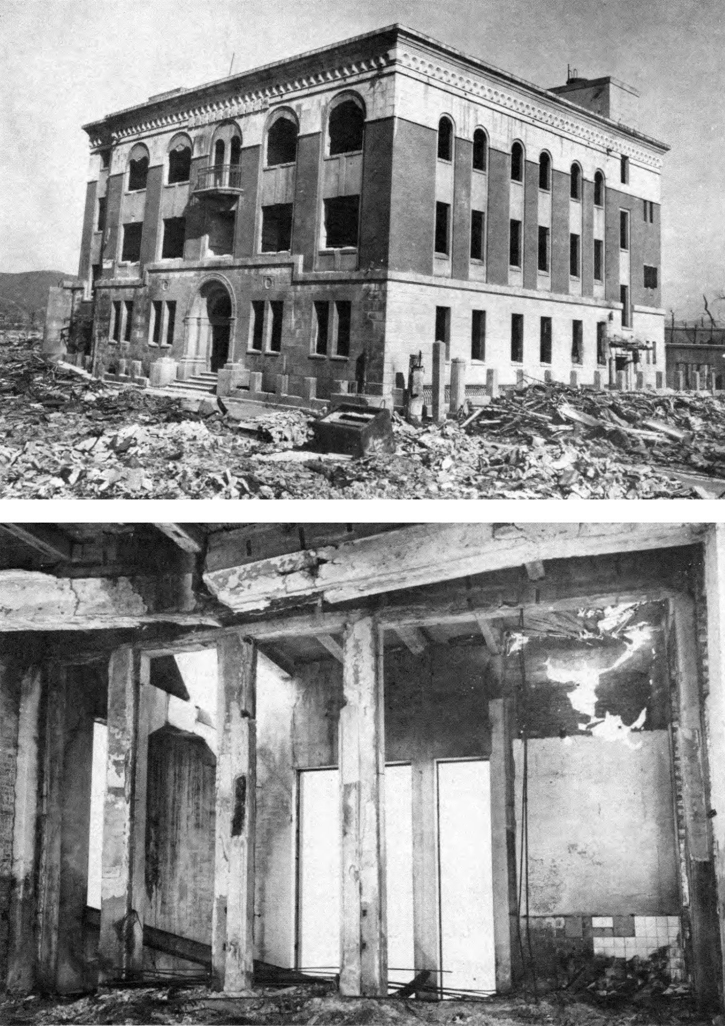
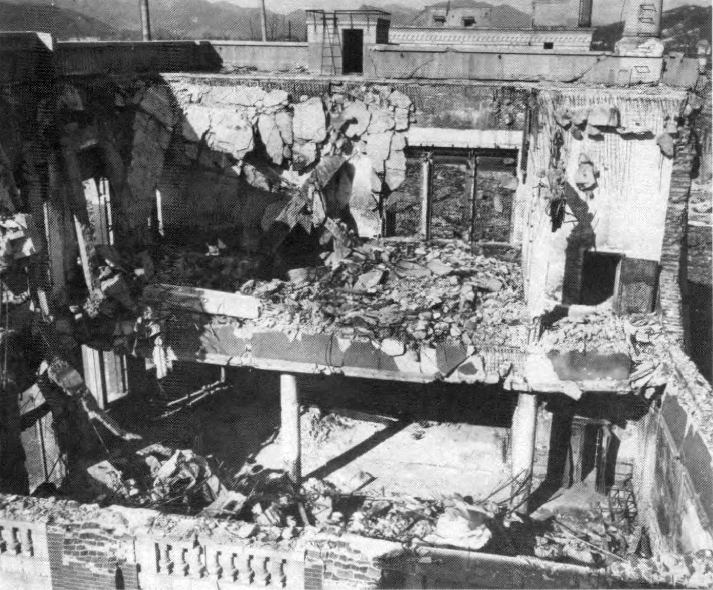
5.20 There were many multistory, reinforced-concrete frame buildings of several types in Hiroshima and a smaller number in Nagasaki. They varied in resistance to blast according to design and construction, but they generally suffered remarkedly little damage externally. Close to ground zero, however, there was considerable destruction of the interior and contents due to the entry of blast through doors and window openings and to subsequent fires. An exceptionally strong structure of earthquake-resistant (aseismic) design, located some 640 feet from ground zero in Hiroshima, is seen in Fig. 5.20a. Although the exterior walls were hardly damaged, the roof was depressed and the interior was destroyed. More typical of reinforced-concrete frame construction in the United States was the building shown in Fig. 5.20b at about the same distance from ground zero. This suffered more severely than the one of aseismic design.

5.21 A factor contributing to the blast resistance of many reinforced concrete buildings in Japan was the construction code established after the severe earthquake of 1923. The height of new buildings was limited to 100 feet and they were designed to withstand a lateral force equal to 10 percent of the vertical load. In addition, the recognized principles of stiffening by diaphragms and improved framing to provide continuity were specified. The more important buildings were well designed and constructed according to the code. However, some were built without regard to the earthquake-resistant requirements and these were less able to withstand the blast wave from the nuclear explosion.
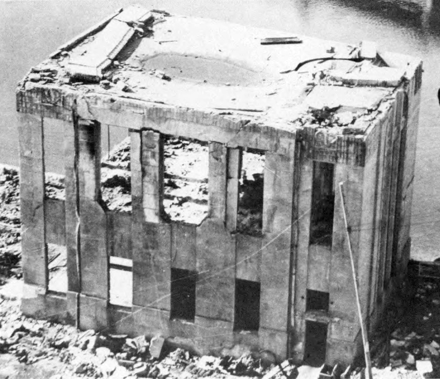
5.22 Close to ground zero the vertical component of the blast was more significant and so greater damage to the roof resulted from the downward force (Fig. 5.22a) than appeared farther away. Depending upon its strength, the roof was pushed down and left sagging or it failed completely. The remainder of the structure was less damaged than similar buildings farther from the explosion because of the smaller horizontal (lateral) forces. At greater distances, from ground zero, especially in the region of Mach reflection, the consequences of horizontal loading were apparent (Fig. 5.22b).
5.23 In addition to the failure of roof slabs and the lateral displacement of walls, numerous other blast effects were observed. These included bending and fracture of beams, failure of columns, crushing of exterior wall panels, and failure of floor slabs (Fig. 5.23). Heavy damage to false ceilings, plaster, and partitions occurred as far out as 9,000 feet (1.7 miles) from ground zero, and glass windows were generally broken out to a distance of 3¾ miles and in a few instances out to 8 miles.
5.24 The various effects just described have referred especially to reinforced-concrete structures. This is because the buildings as a whole did not collapse, so that other consequences of the blast loading could be observed. It should be pointed out, however, that damage of a similar nature also occurred in structures of the other types described below.
MULTISTORY, STEEL-FRAME BUILDINGS
5.25 There was apparently only one steel-frame structure having more than two stories in the Japanese cities exposed to nuclear explosions. This was a five-story structure in Nagasaki at a distance of 4,500 feet (0.85 mile) from ground zero (Fig. 5.25). The only part of the building that was not regarded as being of heavy construction was the roof, which was of 4-inch thick reinforced concrete supported by unusually light steel trusses. The downward failure of the roof, which was dished 3 feet, was the only important structural damage suffered.
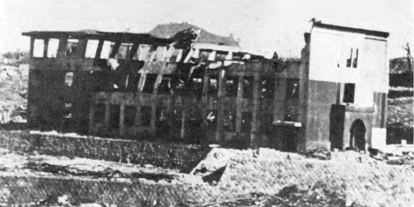
5.26 Reinforced-concrete frame buildings at the same distance from the explosion were also undamaged, and so there is insufficient evidence to permit any conclusions to be drawn as to the relative resistance of the two types of construction. An example of damage to a two-story, steel-frame structure is shown in Fig. 5.26. The heavy walls of the structure transmitted their loads to the steel frame, the columns of which collapsed. Weakening of unprotected steel by fire could have contributed significantly to the damage to steel-frame structures (§ 5.31 ).
BUILDING WITH LOAD-BEARING WALLS
5.27 Small structures with light load-bearing walls offered little resistance to the nuclear blast and, in general, collapsed completely. Large buildings of the same type, but with cross walls and of somewhat heavier construction, were more resistant but failed at distances up to 6,300 feet (1.2 miles) from ground zero. Cracks were observed at the junctions of cross walls and sidewalls when the building remained standing. It is apparent that structures with load-bearing walls possess few of the characteristics that would make them resistant to collapse when subjected to large lateral loads.
INDUSTRIAL STRUCTURES
JAPANESE EXPERIENCE
5.28 In Nagasaki there were many buildings of the familiar type used for industrial purposes, consisting of a steel frame with roof and siding of corrugated sheet metal or of asbestos cement. In some cases, there were rails for gantry cranes, but the cranes were usually of low capacity. In general, construction of industrial-type buildings was comparable to that in the United States.
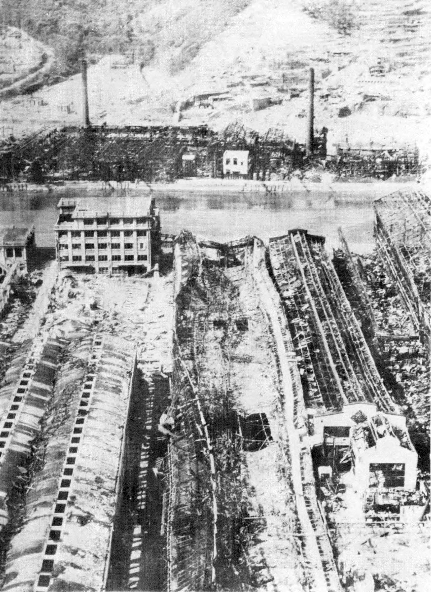
5.29 Severe damage of these structures occurred up to a distance of about 6,000 feet (1.14 miles) from ground zero. Moderately close to ground zero, the buildings were pushed over bodily, and at greater distances they were generally left leaning away from the source of the blast (Fig. 5.29). The columns being long and slender offered little resistance to the lateral loading. Sometimes columns failed due to a lateral force causing flexure, combined with a simultaneous small increase in the downward load coming from the impact of the blast on the roof. This caused buckling and, in some instances, complete collapse. Roof trusses were buckled by compression resulting from lateral blast loading on the side of the building facing the explosion.
5.30 A difference was noted in the effect on the frame depending upon whether a frangible material, like asbestos cement, or a material of high tensile strength, such as corrugated sheet-iron, was used for roof and siding. Asbestos cement broke up more readily permitting more rapid equalization of pressure and, consequently, less structural damage to the frame.
5.31 Fire caused heavy damage to unprotected steel members, so that it was impossible to tell exactly what the blast effect had been. In general, steel frames were badly distorted and would have been of little use, even if siding and roofing material had been available for repairs.
5.32 In some industrial buildings wood trusses were used to support the roof. These were more vulnerable to blast because of poor framing and connections, and were readily burned out by fire. Concrete columns were employed in some cases with steel roof trusses; such columns appeared to be more resistant to buckling than steel, possibly because the strength of concrete is decreased to a lesser extent by fire than is that of steel.
5.33 Damage to machine tools was caused by debris, resulting from the collapse of roof and siding, by fire in wood-frame structures, and by dislocation and overturning as a result of damage to the building. In many instances the machine tools were beltdriven, so that the distortion of the building pulled the machine tool off its base, damaging or overturning it.
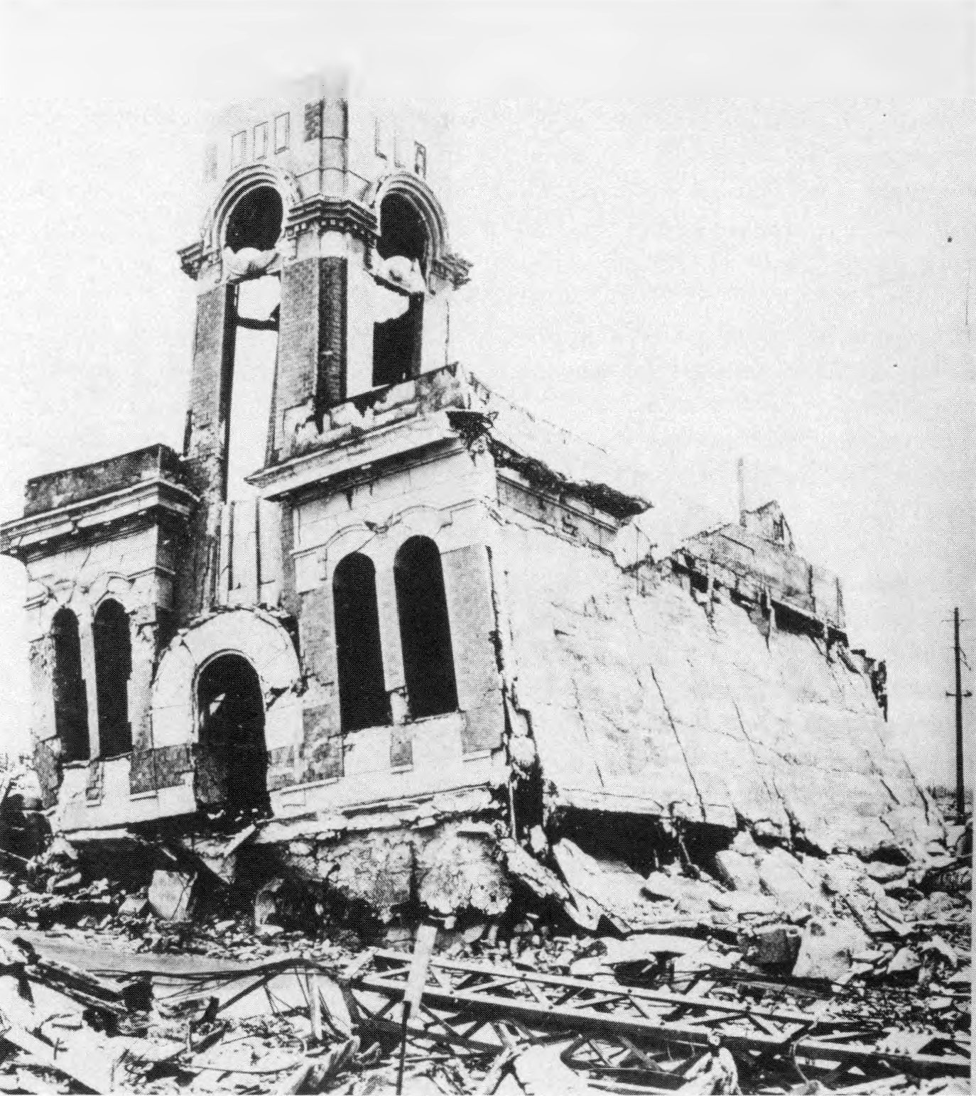
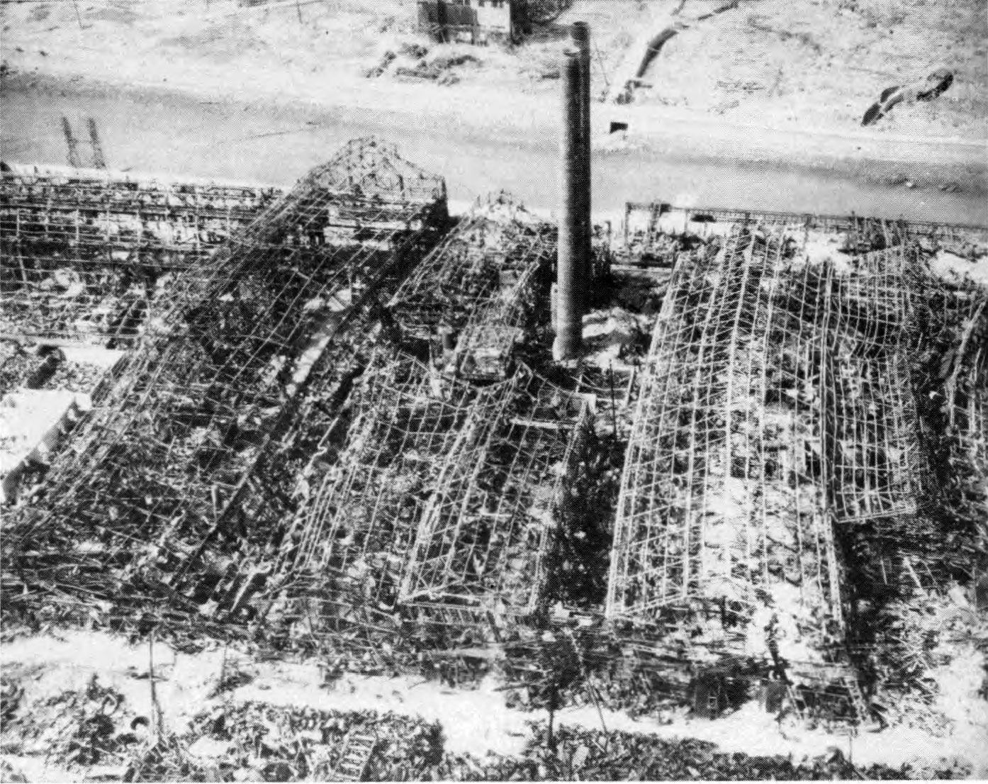
5.34 Smokestacks, especially those of reinforced concrete, proved to have considerable blast resistance (Fig. 5.34a). Because of their shape, they are subjected essentially to drag loading only and, if sufficiently strong, their long period of vibration makes them less sensitive to blast than many other structures. An example of extreme damage to a reinforced-concrete stack is shown in Fig. 5.34b. Steel smokestacks performed reasonably well, but being lighter in weight and subject to crushing were not comparable to reinforced concrete. On the whole, well-constructed masonry stacks withstood the blast somewhat better than did those made of steel.

NEVADA TESTS
5.35 A considerable amount of information on the blast response of structures of several different kinds was obtained in the studies made at the Nevada Test Site in 1953 and in 1955. The nuclear device employed in the test of March 17, 1953, was detonated at the top of a 300-foot tower; the energy yield was about 16 kilotons. In the test of May 5, 1955, the explosion took place on a 500-foot tower and the yield was close to 29 kilotons. In each case, air pressure measurements made possible a correlation, where it was justified, between the blast damage and the peak overpressure.
5.36 Three types of metal buildings of standard construction, such as are used for various commercial and industrial purposes, were exposed at peak overpressures of 3.1 and 1.3 pounds per square inch. The main objectives of the tests, made in 1955, were to determine the blast pressures at which such structures would survive, in the sense that they could still be used after moderate repairs, and to provide information upon which could be based improvements in design to resist blast.
STEEL FRAME WITH ALUMINUM PANELS
5.37 The first industrial type building had a conventional rigid steel frame, which is familiar to structural engineers, with aluminum-sheet panels for roofing and siding (Fig. 5.37a). At a blast overpressure of 3.1 pounds per square inch this building was severely damaged. The welded and bolted steel frame remained standing, but was badly distorted and pulled away from the concrete footings. On the side facing the explosion the deflection was about I foot at the eaves (Fig. 5.37b).

5.38 At a peak overpressure of 1.3 pounds per square inch the main steel frame suffered only slight distortion. The aluminum roofing and siding were not blown off, although the panels were disengaged from the bolt fasteners on the front face of the steel columns and girts (horizontal connecting members). Wall and roof panels facing the explosion were dished inward. The center girts were torn loose from their attachments to the columns in the front of the building. The aluminum panels on the side walls were dished inward slightly, but on the rear wall and rear slope of the roof, the sheeting was almost undisturbed.
5.39 As presently designed, structures of this type may be regarded as being repairable, provided they are not exposed to blast pressures exceeding 1 pound per square inch. Increased blast resistance would probably result from improvement in the design of girts and purlins (horizontal members supporting rafters), in particular. Better fastening between sill and wall footing and increased resistance to transverse loading would also be beneficial.
SELF-FRAMING WITH STEEL PANELS
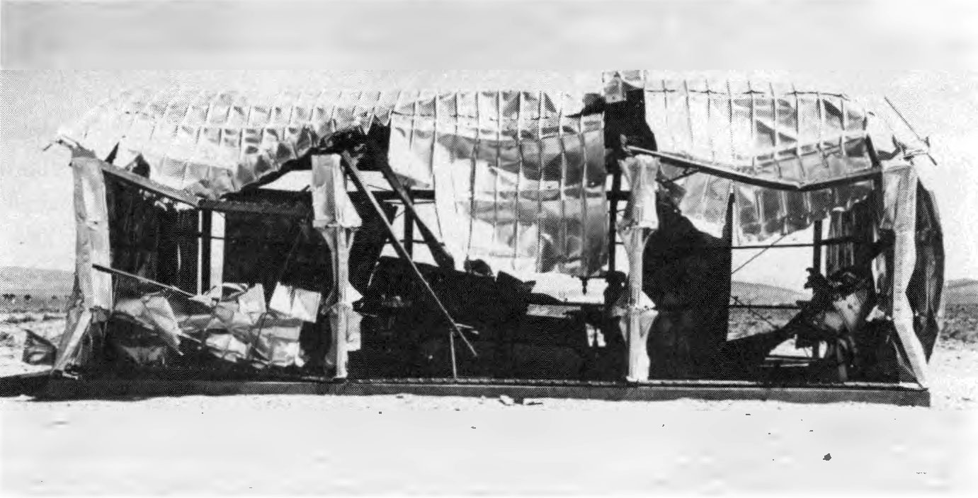
5.40 A frameless structure with self-supporting walls and roof of light, channel-shaped, interlocking, steel panels (16 inches wide) represented the second standard type of industrial building (Fig. 5.40a). The one subjected to 3.1 pounds per square inch peak overpressure (and a dynamic pressure of 0.2 pound per square inch) was completely demolished (Fig. 5.40b). One or two segments of wall were blown as far as 50 feet away, but, in general, the bent and twisted segments of the building remained approximately in their original locations. Most of the wall sections were still attached to their foundation bolts on the side and rear walls of the building. The roof had collapsed completely and was resting on the machinery in the interior.
5.41 Although damage at 1.3 pounds per square inch peak overpressure was much less, it was still considerable in parts of the structure. The front wall panels were buckled inward from 1 to 2 feet at the center, but the rear wall and rear slope of the roof were undamaged. In general, the roof structure remained intact, except for some deflection near the center.
5.42 It appears that the steel panel type of structure is repairable if exposed to overpressures of not more than about ¾ to 1 pound per square inch. The buildings are simple to construct but they do not hold together well under blast. Blast-resistant improvements would seem to be difficult to incorporate while maintaining the essential simplicity of design.
SELF-FRAMING WITH CORRUGATED STEEL PANELS
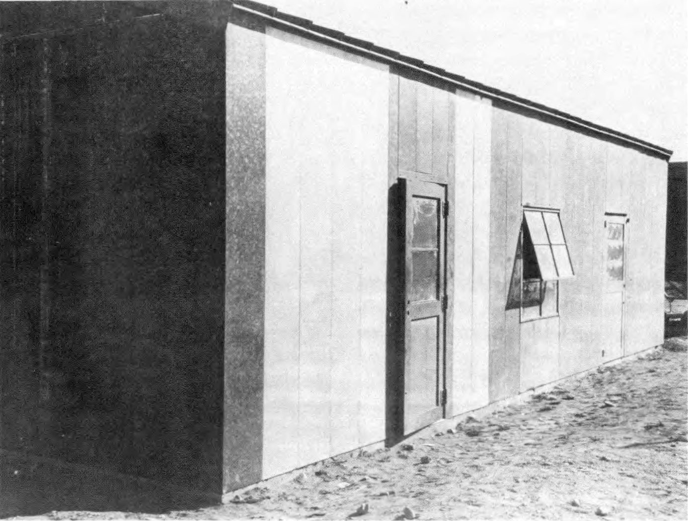
5.43 The third type of industrial building was a completely frameless structure made of strong, deeply-corrugated 43-inch wide panels of 16-gauge steel sheet. The panels were held together with large bolt fasteners at the sides and at the eaves and roof ridge. The wall panels were bolted to the concrete foundation. The entire structure was self-supporting, without frames, girts, or purlins (Fig. 5.43).
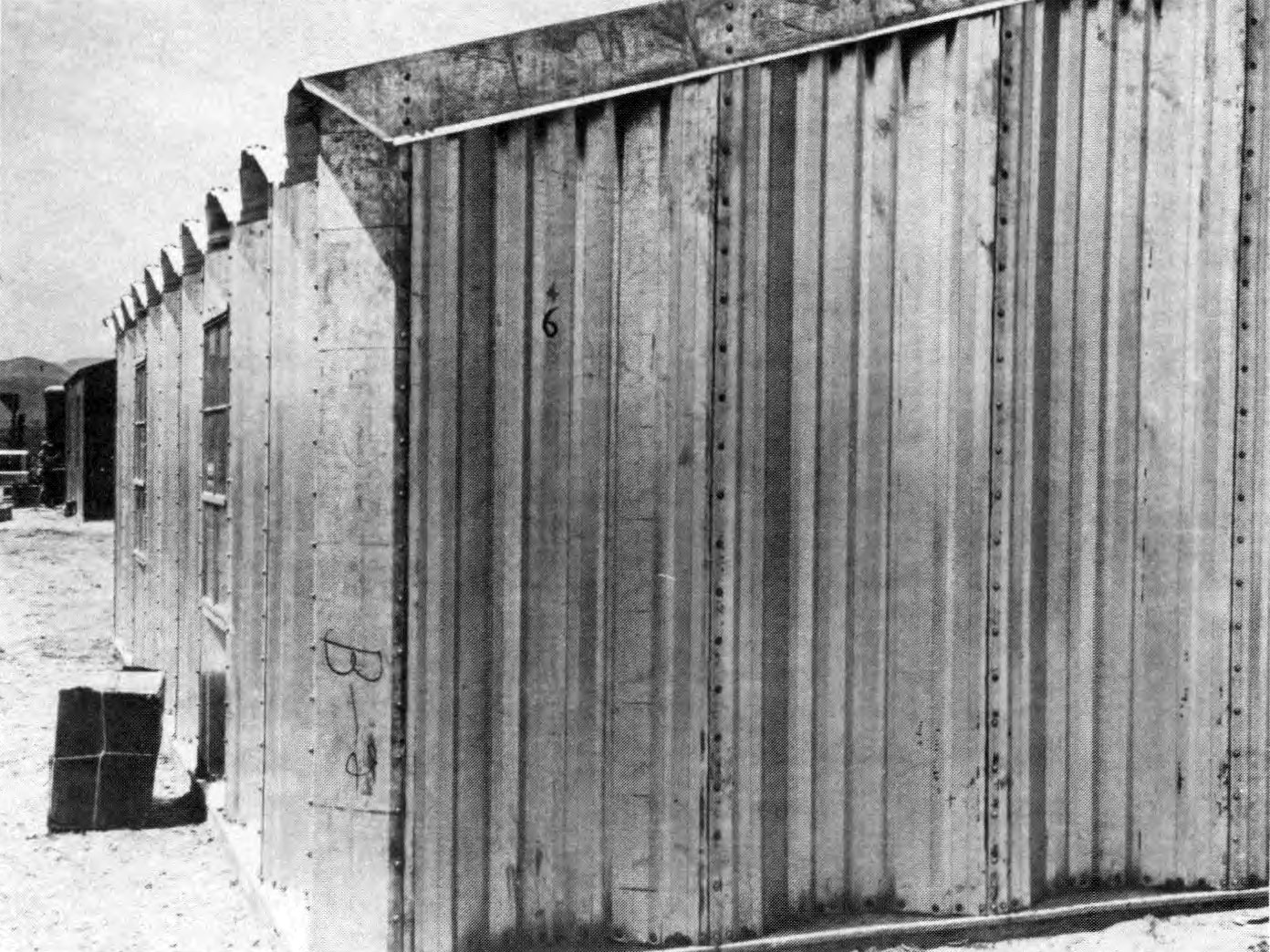
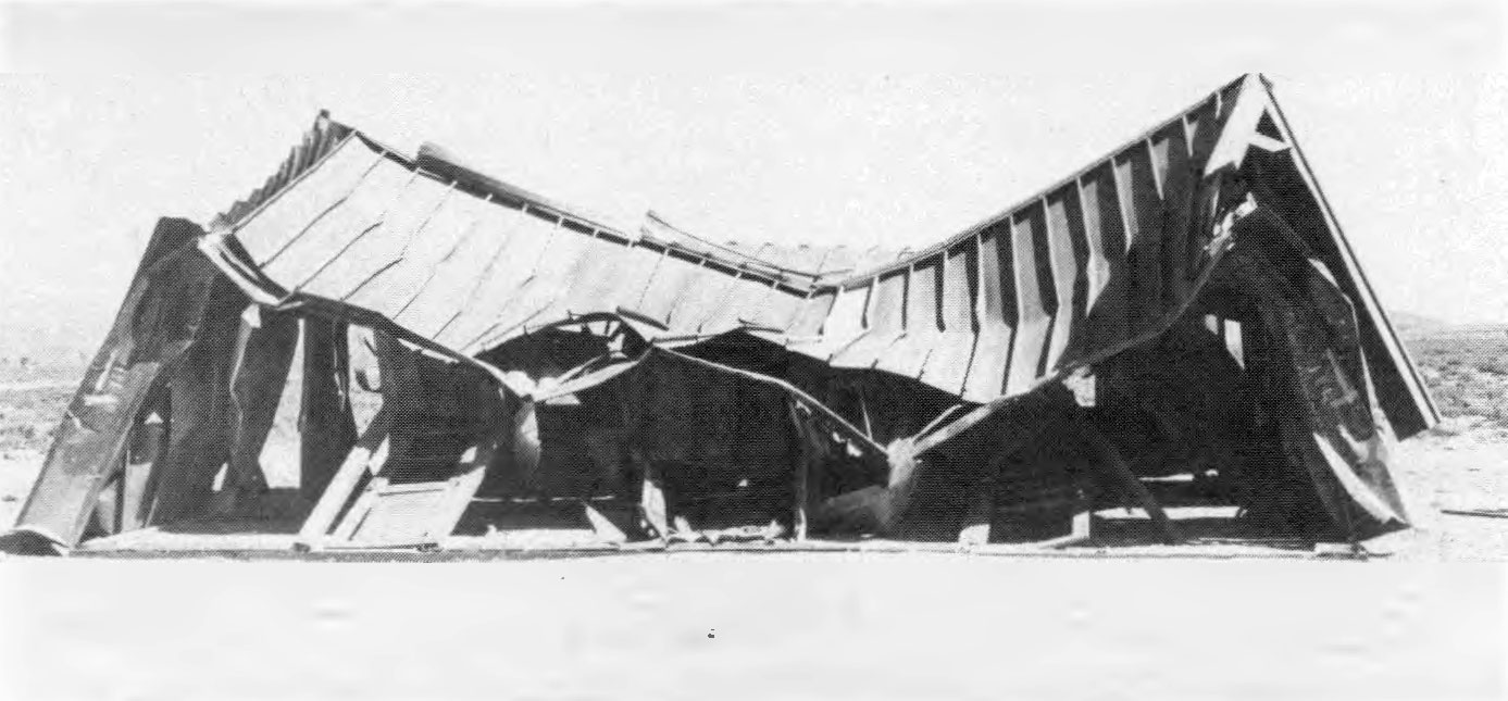
5.44 At a peak overpressure of 3.1 and a dynamic pressure of 0.2 pound per square inch a structure of this type was badly damaged, but all the pieces remained bolted together, so that the structure still provided good protection from the elements for its. contents. The front slope of the roof was crushed downward, from 1 to 2 feet, at midsection, and the ridge line suffered moderate deflection. The rear slope of the roof appeared to be essentially undamaged (Fig. 5.44).
5.45 The front and side walls were buckled inward several inches, and the door in the front was broken off. All the windows were damaged to some extent, although a few panes in the rear remained in place.
5.46 Another building of this type, exposed to 1.3 pounds per square inch peak overpressure, experienced little structural damage. The roof along the ridge line showed indications of downward deflections of only 1 or 2 inches, and there was no apparent buckling of roof or wall panels. Most of the windows were broken, cracked, or chipped. Replacement of the glass where necessary and some minor repairs would have rendered the building completely serviceable.
5.47 The corrugated steel, frameless structure proved to be the most blast-resistant of those tested. It is believed that, provided the overpressure did not exceed about 3 pounds per square inch, relatively minor repairs would make possible continued use of the building. Improvement in the design of doors and windows, so as to reduce the missile hazard from broken glass, would be advantageous.
POSITIVE PHASE DURATION TESTS
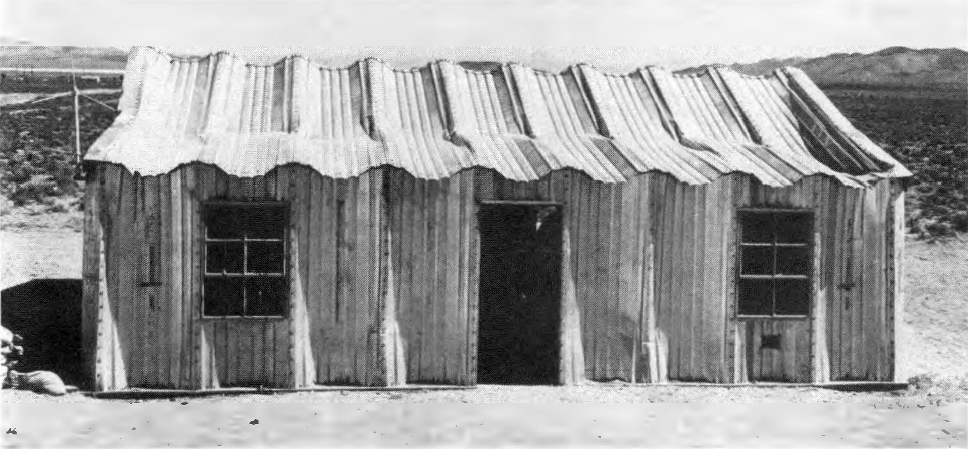
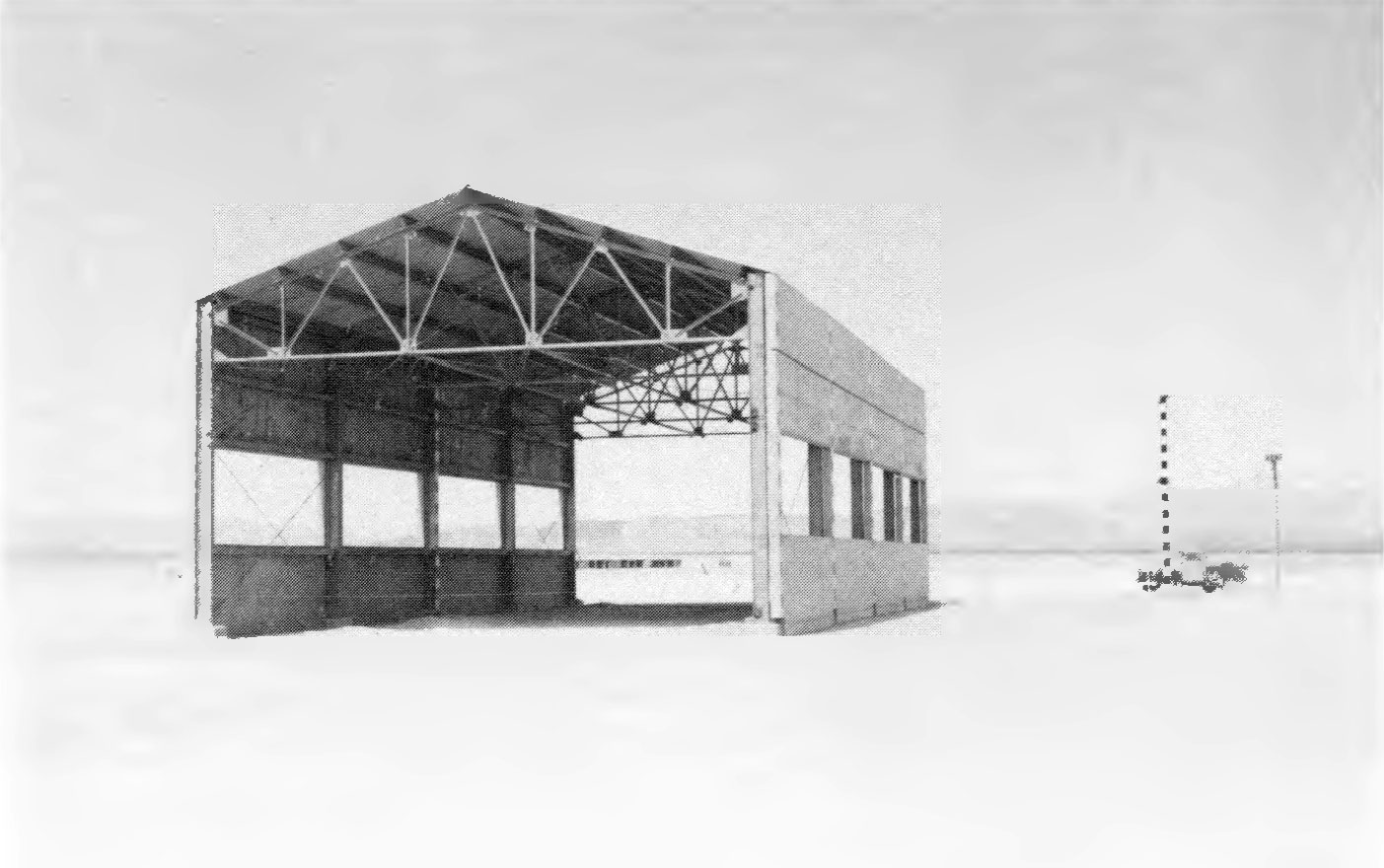
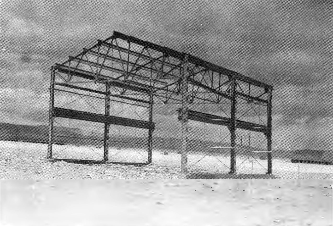
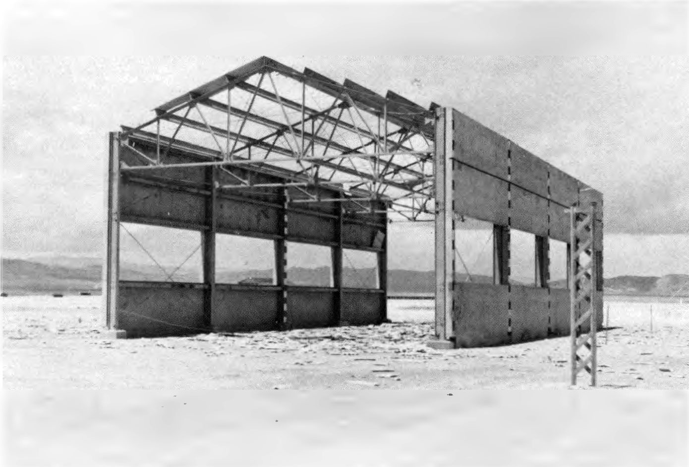
5.48 Tests were carried out at Nevada in 1955 and at Eniwetok Atoll in the Pacific in 1956 to investigate the effect of the duration of the positive overpressure phase of a blast wave on damage. Typical drag-type structures were exposed, at approximately the same overpressure, to nuclear detonations in the kiloton and megaton ranges. Two representative types of small industrial buildings were chosen for these tests. One had a steel frame covered with siding and roofing of a frangible material and was considered to be a drag-type structure (Fig. 5.48a). The other had the same steel frame and roofing, but it had concrete siding with a window opening of about 30 percent of the wall area; this was regarded as a semidrag structure (Fig. 5.48b).
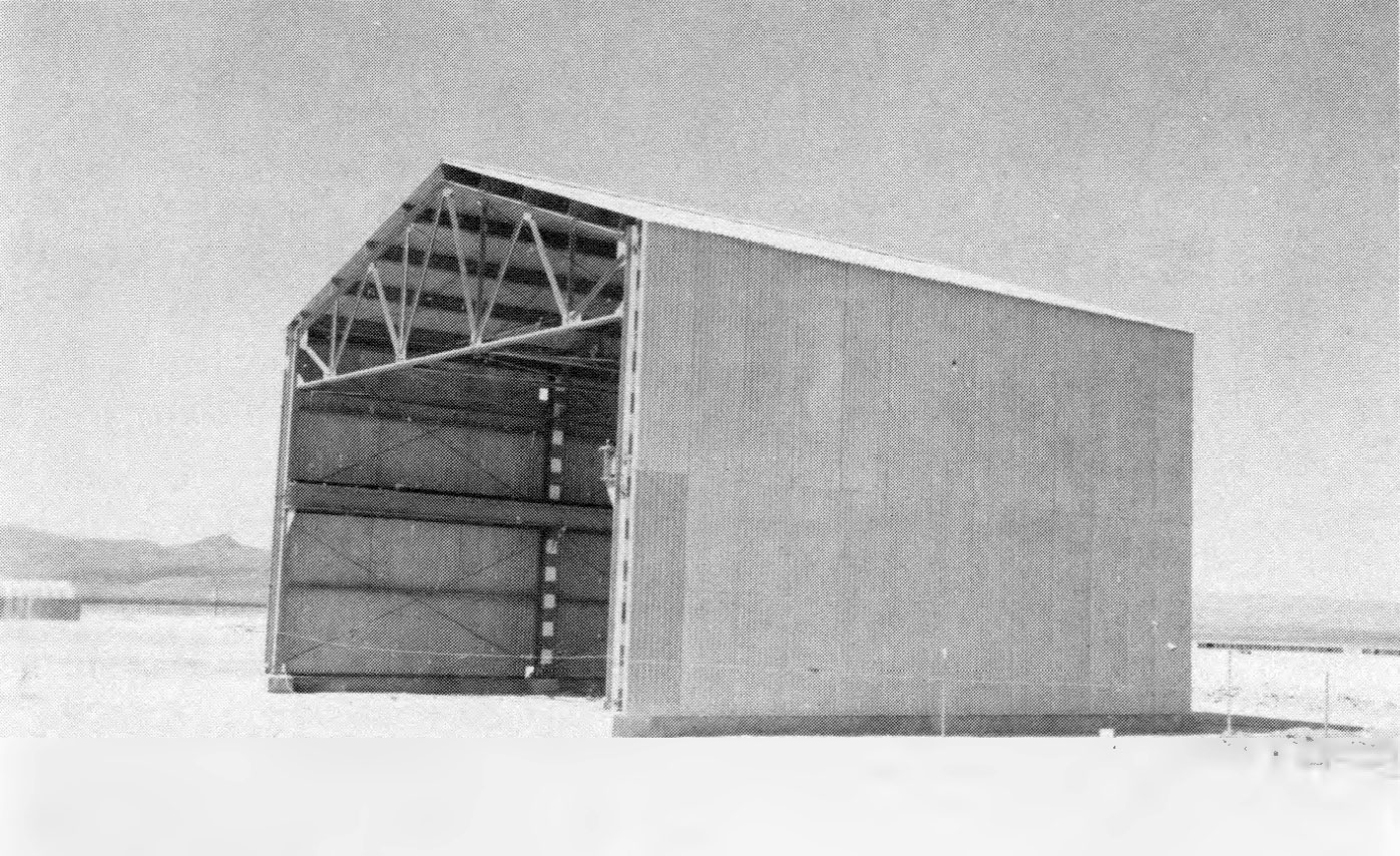
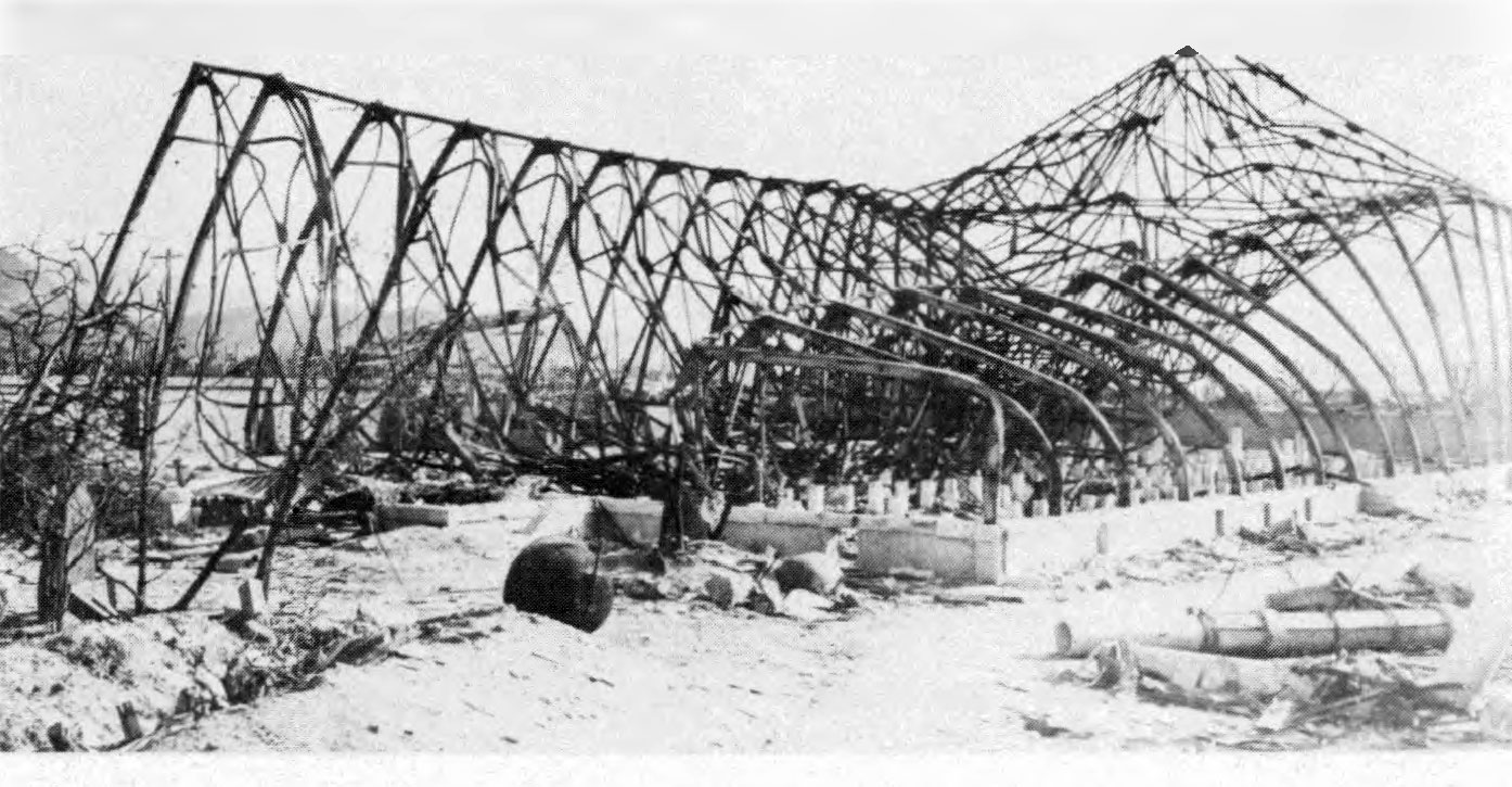
5.49 In the Nevada tests, with kiloton yield weapons, the first structure was subjected to a peak overpressure of about 6.5 and a dynamic pressure of 1.1 pounds per square inch; the positive phase duration of the blast wave was 0.9 second. A permanent horizontal deflection of about 15 inches occurred at the top of the columns. The column anchor bolts failed, and yielding was found between the lower chord (horizontal member of the roof truss) and column connections. The girts on the windward side were severely damaged and all of the siding was completely blown off (Fig. 5.49).
5.50 The second building, with the stronger siding, was exposed in Nevada to a peak overpressure loading of about 3.5 and a dynamic pressure of O. 3 pounds per square inch, with a positive phase duration of 1 second. Damage to this structure was small (Fig. 5.50). Although almost the whole of the frangible roof was blown off, the only other damage observed was a small yielding at some connections and column bases.
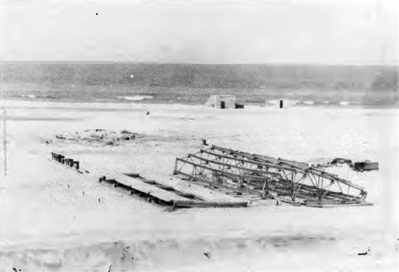
5.51 Structures of the same type were subjected to similar pressures in the blast wave from a megaton range explosion at Eniwetok; namely, a peak overpressure of 6.1 and a dynamic pressure of 0.6 pounds per square inch for the drag-type building, and 5 and 0.5 pounds per square inch, respectively, for the semidrag structure. However, the positive phase now lasted several seconds as compared with about 1 second in the Nevada tests. Both structures suffered complete collapse (Figs. 5.51a and b). Distortion and breakup occurred throughout, particularly of columns and connections. It was concluded, therefore, that damage to drag-sensitive structures can be enhanced, for a given peak overpressure value, if the duration of the positive phase of the blast wave is increased (cf. § 4.13).

RESIDENTIAL STRUCTURES
JAPANESE EXPERIENCE
5.52 There were many wood framed residential structures with adobe walls in the Japanese cities which were subjected to nuclear attack, but such a large proportion were destroyed by fire that very little detailed information concerning blast damage was obtained. It appeared that, although the quality of the workmanship in framing was usually high, little attention was paid to good engineering principles. On the whole, therefore, the construction was not well adapted to resist wracking action (distortion). For example, mortise and tenon joints were weak points in the ing in an overall weakening (Fig. 5.52).

5.53 In Kagasaki, dwellings collapsed at distances up to 7,500 feet (1.4 miles) from ground zero, where the peak overpressure was estimated to be about 3 pounds per square inch, and there was severe structural damage up to 8,500 feet (1.6 miles). Roofs, wall panels, and partitions were damaged out to 9,000 feet (1.7 miles), where the overpressure was approximately 2 pounds per square inch, but the buildings would probably have been habitable with moderate repairs.
NEVADA TESTS
5.54 The main objectives of the tests made in Nevada in 1953 and 1955 (§ 5.35) on residential structures were as follows: (1) to determine the elements most susceptible to blast damage and consequently to devise methods for strengthening structures of various types; (2) to provide information concerning the amount of damage to residences that might be expected as a result of a nuclear explosion and to what extent these structures would be subsequently rendered habitable without major repairs; and (3) to determine how persons remaining in their houses during a nuclear attack might be protected from the effects of blast and radiations. Only the first two of these aspects of the tests will be considered here, since the present chapter deals primarily with blast effects.
TWO-STORY, WOOD-FRAME HOUSE: 1953 TEST
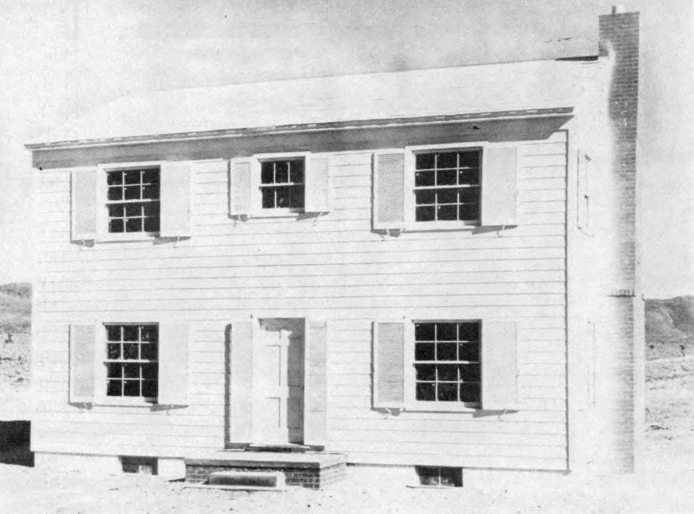
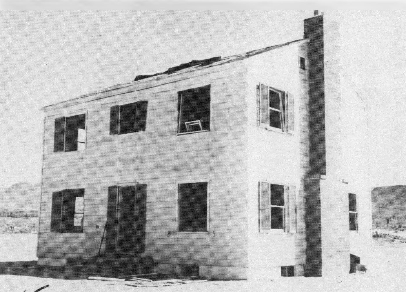
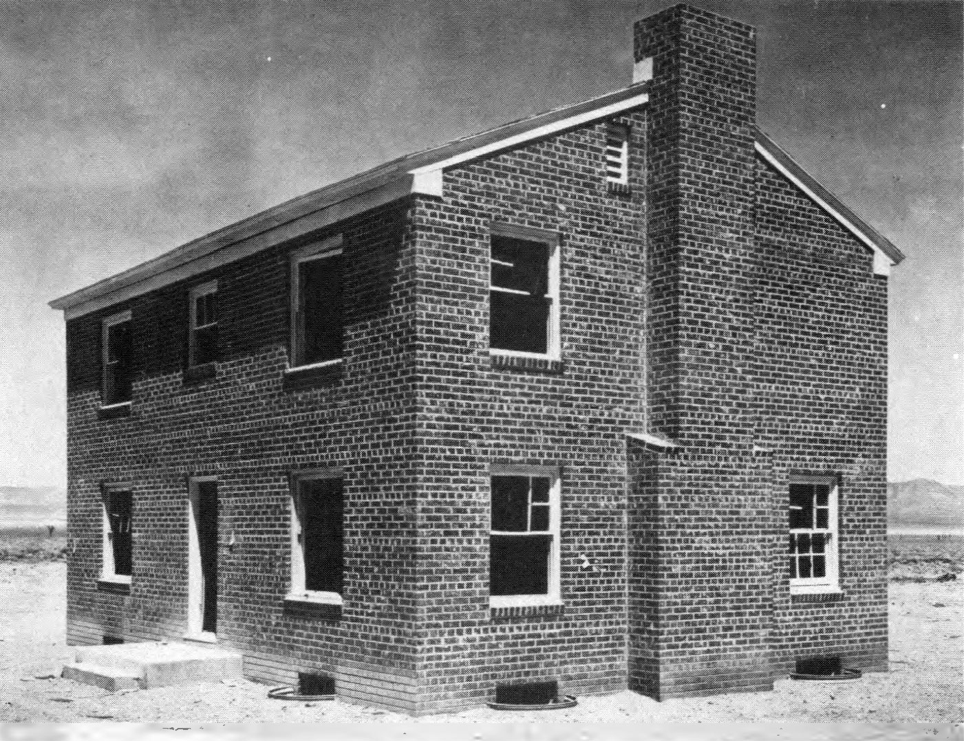
5.55 In the 1953 test, two essentially identical houses, of a type common in the United States, were placed at different locations. They were of typical wood-frame construction, with two stories, basement, and brick chimney (Fig. 5.55). The interiors were plastered but not painted. Since the tests were intended for studying the effects of blast, precautions were taken to prevent the houses from burning. The exteriors were consequently painted white (except for the shutters), to reflect the thermal radiation. For the same purpose, the windows facing the explosion were equipped with metal venetian blinds having an aluminum finish. In addition, the houses were roofed with light-gray shingles; these were of asbestos cement for the house nearer to the explosion where the chances of fire were greater, whereas asphalt shingles were used for the other house. There were no utilities of any kind.
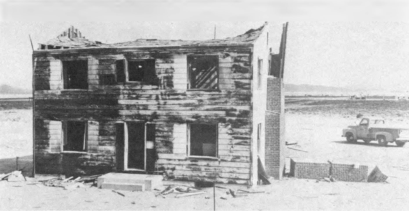
5.56 One of the two houses was located in the region of Mach reflection where the peak incident overpressure was close to 5 pounds per square inch. It was expected, from the effects in Japan, that this house would be almost completely destroyed—as indeed it was—but the chief purpose was to see what protection might be obtained by persons in the basement.
5.57 Some indication of the blast damage suffered by this dwelling can be obtained from Fig. 5.57. It is apparent that the house was ruined beyond repair. The first story was completely demolished and the second story, which was very badly damaged, dropped down on the first floor debris. The roof was blown off in several sections which landed at both front and back of the house. The gable end walls were blown apart and outward, and the brick chimney was broken into several pieces.

5.58 The basement walls suffered some damage above grade, mostly in the rear, i.e., away from the explosion. The front basement wall was pushed in slightly, but was not cracked except at the ends. The joists supporting the first floor were forced downward probably because of the air pressure differential between the first floor and the largely enclosed basement, and the supporting pipe columns were inclined to the rear. However, only in limited areas did a complete breakthrough from first floor to basement occur. The rest of the basement was comparatively clear and the shelters located there were unaffected.
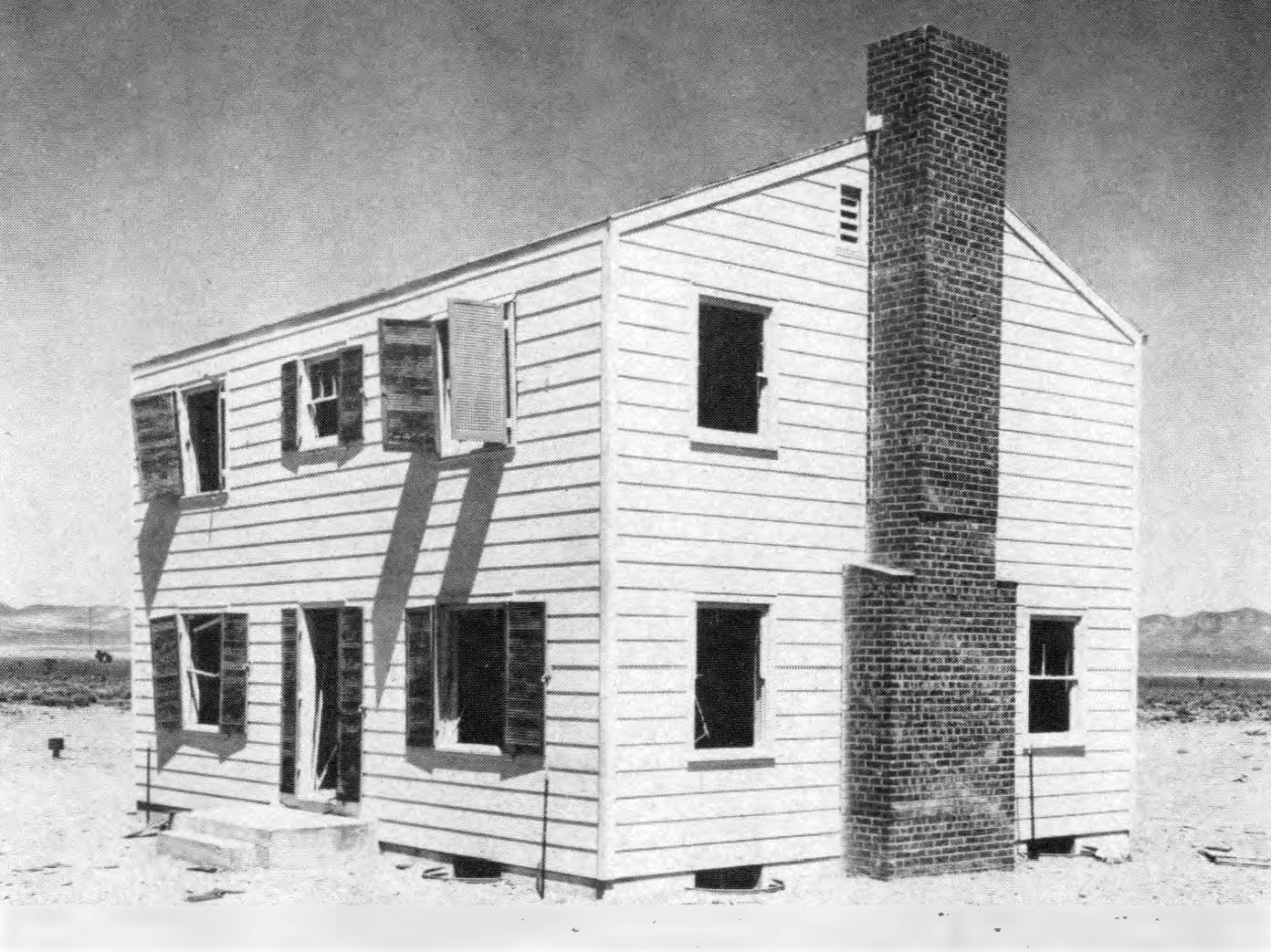
5.59 The second house, exposed to an incident peak overpressure of 1.7 pounds per square inch, was badly damaged both internally and externally, but it remained standing (Fig. 5.59). People in the main and upper floors would have suffered injuries ranging from minor cuts from glass fragments to possible fatal injuries from flying debris or as a result of translational displacement of the body as a whole. Some damage would also result to the furnishings and other contents of the house. Although complete restoration would have been very costly. it is believed that, with the window and door openings covered, and shoring in the basement, the house would have been habitable under emergency conditions.
5.60 The most obvious damage was suffered by doors and windows, including sash and frames. The front door was broken into pieces and the kitchen and basement entrance doors were torn off their hinges. Damage to interior doors varied; those which were open before the explosion suffered least. Window glass throughout the house was broken into fragments, and the force on the sash, especially in the front of the house, dislodged the frames.
5.61 Principal damage to the first floor system consisted of broken joists. The second-story system suffered relatively little in structural respects, although windows were broken and plaster cracked. Damage to the roof consisted mainly of broken rafters (2 x 6 inches with 16-inch spacing).
5.62 The basement showed no signs of damage except to the windows, and the entry door and frame. The shelters in the basement were intact.
TWO-STORY, WOOD-FRAME HOUSE: 1955 TEST
5.63 Based upon the results described above, certain improvements in design were incorporated in two similar wood-frame houses used in the 1955 test. The following changes, which increased the estimated cost of the houses some 10 percent above that for normal construction, were made: (1) improved connection between exterior walls and foundations; (2) reinforced-concrete shear walls to replace the pipe columns in the basement; (3) increase in size and strengthening of connections of firs floor joists; (4) substitution of plywood for lath and plaster; (5) increase in size of rafters (to 2 x 8 inches) and wall studs; and (6) stronger nailing of window frames in wall openings.
5.64 Even with these improvements, it was expected that almost complete destruction would occur at 5 pounds per square inch peak overpressure, and so one of the houses was located where the overpressure at the Mach front would be 4 pounds per square inch. Partly because of the increased strength and partly because of the lower air blast pressure the house did not collapse (Fig. 5.64). But the superstructure was so badly damaged that it could not have been occupied without expensive repair which would not have been economically advisable.
5.65 The other strengthened two story frame house was in a location where the incident peak overpressure was about 2.6 pounds per square inch; this was appreciably greater than the lower overpressure of the 1953 test. Relatively heavy damage was experienced, but the condition of the house was such that it could be made available for emergency shelter by shoring and not too expensive repairs (Fig. 5.65). Although there were differences in detail, the overall damage was much the same degree as that suffered by the corresponding house without the improved features at an overpressure of l. 7 pounds per square inch.
TWO-STORY, BRICK-WALL-BEARING HOUSE: 1955 TEST
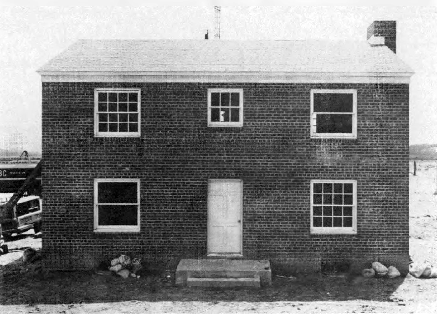
5.66 For comparison with the tests on the two-story, wood-frame structures made in Nevada in 1953, two brick-wall-bearing houses of conventional construction, similar in size and layout, were exposed to 5 and 1.7 pounds per square inch peak overpressure, respectively, in the 1955 tests (Fig. 5.66). The exterior walls were of brick veneer and cinder block and the foundation walls of cinder block; the floors, partitions, and roof were wood-framed.
5.67 At an incident peak overpressure of 5 pounds per square inch, the brick-wall house was damaged beyond repair (Fig. 5.67). The side and back walls failed outward. The front wall failed initially inward, but its subsequent behavior was obscured by dust. The final location of the debris from the front wall is therefore uncertain, but very little fell on the floor framing. The roof was demolished and blown off. the rear part landing 50 feet behind the house. The first floor had partially collapsed into the basement as a result of fracturing of the floor joists at the center of the spans and the load of the second floor which fell upon it. The chimney was broken into several large sections.

5.68 Farther from the explosion, where the peak overpressure was 1.7 pounds per square inch, the corresponding structure was damaged to a considerable extent. Nevertheless, its condition was such that it could be made available for habitation by shoring and some fairly inexpensive repairs (Fig. 5.68).
ONE-STORY, WOOD-FRAME (RAMBLER TYPE) HOUSE: 1955 TEST
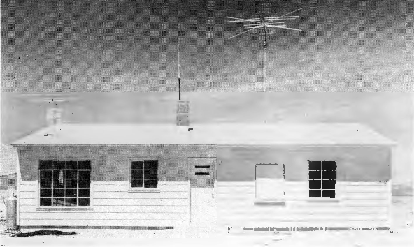
5.69 A pair of the so-called “rambler” type, single-story. wood-frame houses were erected at the Nevada Test Site on concrete slabs poured in place at grade. They were of conventional design except that each contained a shelter. above ground, consisting of the bathroom walls, floor, and ceiling of reinforced concrete with blast door and shutter (Fig. 5.69).
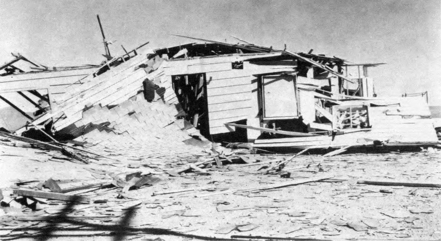
5.70 When exposed to an incident peak overpressure of about 5 pounds per square inch, one of these houses was demolished beyond repair. However, the bathroom shelter was not damaged at all. Although the latch bolt on the blast shutter failed, leaving the shutter unfastened, the window was still intact. The roof was blown off and the rafters were split and broken. The side walls at gable ends were blown outward, and fell to the ground. A portion of the front wall remained standing, although it was leaning away from the direction of the explosion (Fig. 5.70).
5.71 The other house of the same type, subjected to a peak overpressure of 1.7 pounds per square inch, did not suffer too badly and it could easily have been made habitable. Windows were broken, doors blown off their hinges, and plaster-board walls and ceilings were badly damaged. The main structural damage was a broken midspan rafter beam and distortion of the frame. In addition, the porch roof was lifted 6 inches off its supports.
ONE-STORY, PRECAST CONCRETE HOUSE: 1955 TEST
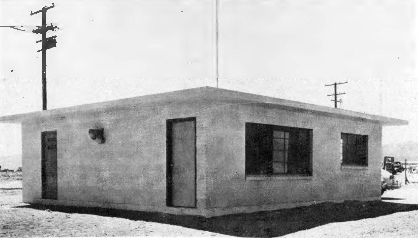
5.72 Another residential type of construction tested in Nevada in 1955 was a single-story house made of precast, lightweight (expanded shale aggregate) concrete wall and partition panels, joined by welded matching steel lugs. Similar roof panels were anchored to the walls by special countersunk and grouted connections. The walls were supported on concrete piers and a concrete floor slab, poured in place on a tamped fill after the walls were erected. The floor was anchored securely to the walls by means of perimeter reinforcing rods held by hook bolts screwed into inserts in the wall panels. The overall design was such as to comply with the California code for earthquake-resistant construction (Fig. 5.72).
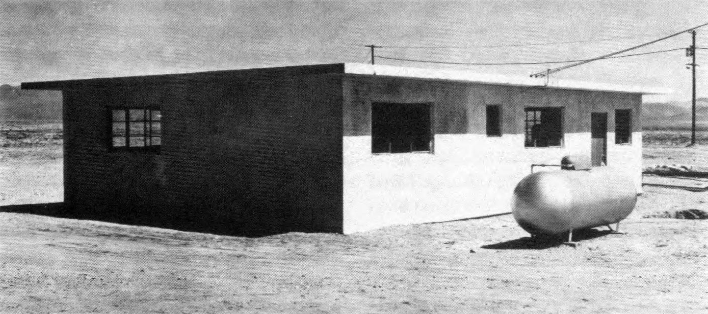
5.73 This house stood up well, even at a peak overpressure of 5 pounds per square inch. By replacement of demolished or badly damaged doors and windows, it could have been made available for occupancy (Fig. 5.73).
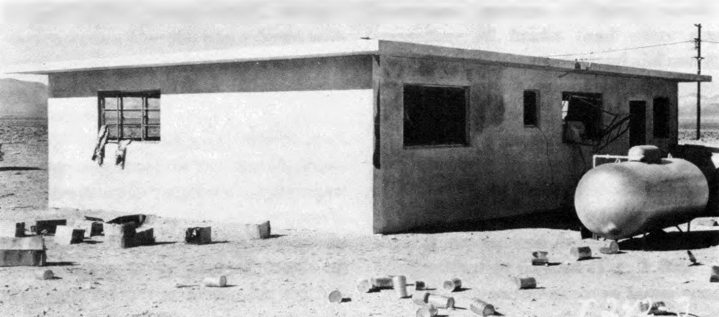
5.74 There was some indication that the roof slabs at the front of the house were lifted slightly from their supports, but this was not sufficient to break any connections. Some of the walls were cracked slightly and others showed indications of minor movement. In certain areas the concrete around the slab connections was spalled, so that the connectors were exposed. The steel window-sash was somewhat distorted, but it remained in place.
5.75 At a peak overpressure of 1.7 pounds per square inch, the precast concrete-slab house suffered relatively minor damage. Glass was broken extensively, and doors were blown off their hinges and demolished, as in other houses exposed to the same air pressure. But, apart from this and distortion of the steel window-sash, the only important damage was spalling of the concrete at the lug connections, i.e., where the sash projected into the concrete.
ONE-STORY, REINFORCED-MASONRY HOUSE: 1955 TEST
5.76 The last type of house subjected to test in 1955 was also of earthquake-resistant design. The floor was a concrete slab, poured in place at grade. The walls and partitions were built of lightweight (expanded shale aggregate) 8-inch masonry blocks, reinforced with vertical steel rods anchored into the floor slab. The walls were also rein-forced with horizontal steel rods at two levels, and openings were spanned by reinforced lintel courses. The roof was made of precast, lightweight concrete slabs, similar to those used in the precast concrete houses described above (Fig. 5.76).
5.77 At a peak overpressure of about 5 pounds per square inch, windows were destroyed and doors blown in the demolished. The steel window sash was distorted, but nearly all remained in place. The house suffered only minor structural damage and could have been made habitable at relatively small cost (Fig. 5.77).
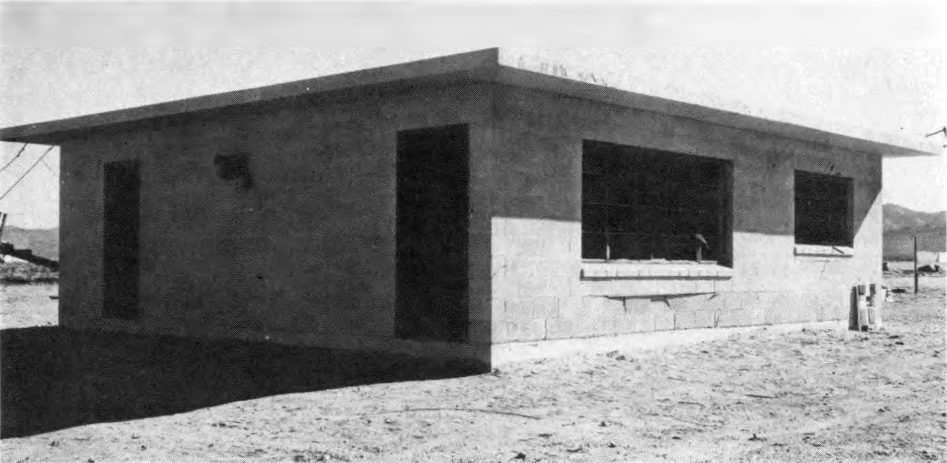
5.78 There was some evidence that the roof slabs had been moved, but not sufficiently to break any connections. The masonry wall under the large window (see Fig. 5.77) was pushed in about 4 inches on the concrete floor slab; this appeared to be due to the omission of dowels between the walls and the floor beneath window openings. Some cracks developed in the wall above the same window, probably as a result of improper installation of the reinforced lintel course and the substitution of a pipe column in the center span of the window.
5.79 A house of the same type exposed to the blast at a peak overpressure of 1.7 pounds per square inch suffered little more than the usual destruction of doors and windows. The steel window-sash remained in place but was distorted, and some spalling of the concrete around lug connections was noted. On the whole, the damage to the house was of a minor character and it could readily have been repaired.
TRAILER-COACH MOBILE HOMES: 1955 TEST
5.80 Sixteen trailer-coaches of various makes, intended for use as mobile homes, were subjected to blast in the 1955 test in Nevada. Nine were located where the peak blast overpressure was 1.7 pounds per square inch, and the other seven where the peak overpressure was about 1 pound per square inch. They were parked at various angles with respect to the direction of travel of the blast wave.
5.81 At the higher overpressure two of the mobile homes were tipped over by the explosion. One of these was originally broadside to the blast, whereas the second, at an angle of about 45°, was of much lighter weight. All the others at both locations remained standing. On the whole, the damage sustained was not of a serious character.
5.82 From the exterior, many of the mobile homes showed some dents in walls or roof, and a certain amount of distortion. There were, however, relatively few ruptures. Most windows were broken, but there was little or no glass in the interior, especially in those coaches having screens fitted on the inside. Where there were no screens or venetian blinds, and particularly where there were large picture windows, glass was found inside.
5.83 The interiors of the mobile homes were usually in a state of disorder due to ruptured panels, broken and upset furniture, and cupboards, cabinets, and wardrobes which had been torn loose and damaged. Stoves, refrigerators, and heaters were not displaced, and the floors were apparently unharmed. The plumbing was, in general, still operable after the explosion. Consequently, by rearranging the displaced furniture, repairing cabinets, improvising window coverings, and cleaning up the debris, all trailer-coaches could have been made habitable for emergency use.
5.84 At the 1 pound per square inch overpressure location some windows were broken, but no major damage was sustained. The principal repairs required to make the mobile homes available for occupancy would be window replacement or improvised window covering.
TRANSPORTATION
LIGHT LAND TRANSPORTATION EQUIPMENT
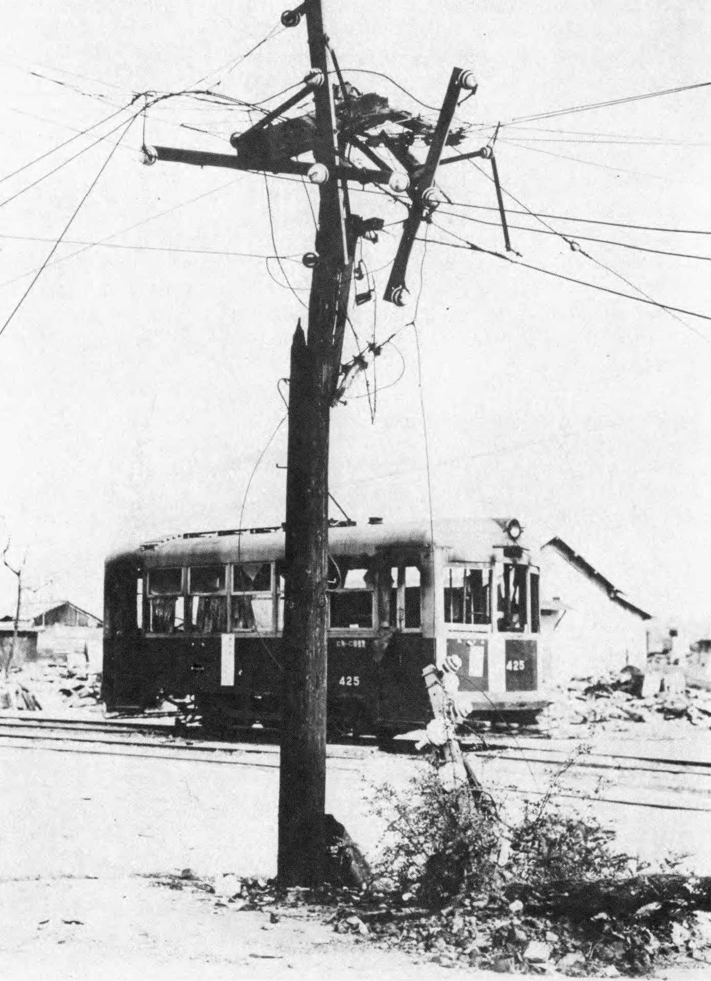
5.85 In Japan, trolley-car equipment was heavily damaged by both blast and fire, although the poles were frequently left standing. Buses and automobiles generally were rendered inoperable by blast and fire as well as by damage caused by flying debris. However, the damage decreased rapidly with distance. An American made automobile was badly damaged and burned at 3,000 feet (0.57 mile) from ground zero, but a similar vehicle at 6,000 feet (I .14 miles) suffered only minor damage.
5.86 Automobiles and buses have been exposed to several of the nuclear test explosions in Nevada, where the conditions, especially as regards damage by fire and missiles, were somewhat different from those in Japan. In the descriptions that follow, distance is related to peak overpressure. In most cases, however, it was not primarily overpressure, but drag forces, which produced the damage. In addition, allowance must be made for the effect of the blast wave precursor (§ 3.79 et seq.). Hence, the damage radii cannot be determined from overpressure alone.
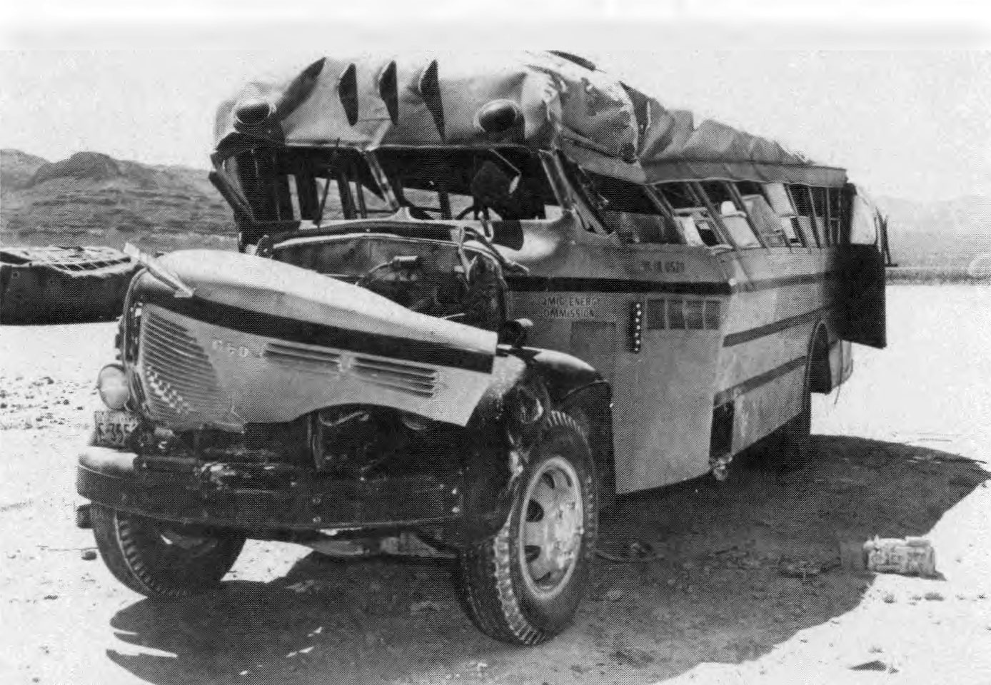
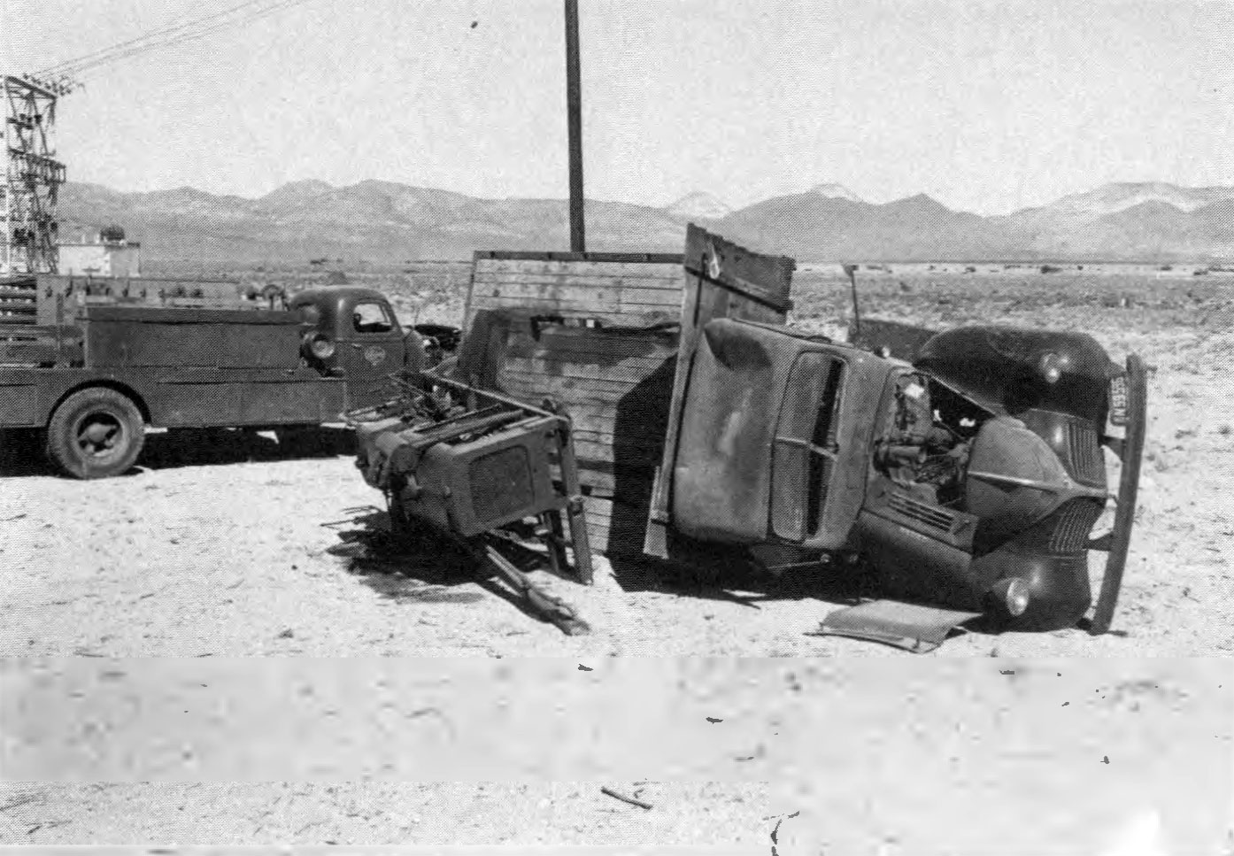
5.87 Some illustrations of the effects of a nuclear explosion on motorized vehicles are shown in Figs. 5.87a and b. At a peak overpressure of 5 pounds per square inch motor vehicles were badly battered, with their tops and sides pushed in, windows broken, and hoods blown open. But the engines were still operable and the vehicles could be driven away after the explosion. Even at higher blast pressures, when the overall damage was greater, the motors appeared to be intact.

5.88 During the 1955 tests in Nevada, studies were made to determine the extent to which various emergency vehicles and their equipment would be available for use immediately following a nuclear attack. The vehicles included a rescue truck, gas and electric utility service or repair trucks, telephone service trucks, and fire pumpers and ladder trucks. One vehicle was exposed to a peak overpressure of about 30 pounds per square inch, two at 5 pounds per square inch, two at 1.7 pounds per square inch, and six at about 1 pound per square inch. It should be emphasized, however, that, for vehicles in general, overpressure is not usually the. sole or even the primary damage mechanism.
5.89 The rescue truck at the 30 pounds per square inch location was completely destroyed, and only one wheel and part of the axle were found after the blast. At 5 pounds per square inch peak overpressure a truck, with an earth-boring machine bolted to the bed, was broadside to the blast. This truck was overturned and somewhat damaged, but still operable (Fig. 5.89). The earth-boring machine was knocked loose and was on its side leaking gasoline and water. At the same location, shown to the left of the overturned truck in Fig. 5.89, was a heavy-duty electric utility truck, facing head-on to the blast. It had the windshield shattered, both doors and cab dished in, the hood partly blown off, and one tool-compartment door dished. There was, however, no damage to tools or equipment and the truck was driven away without any repairs being required.
5.90 At the 1.7 pounds per square inch location, a light-duty electric utility truck and a fire department 75-foot aerial ladder truck sustained minor exterior damage, such as broken windows and dished-in panels. There was no damage to equipment in either case, and both vehicles would have been available for immediate use after an attack. Two telephone trucks, two gas utility trucks, a fire department pumper, and a Jeep firetruck, exposed to a peak overpressure of 1 pound per square inch, were largely unharmed.
5.91 It may be concluded that vehicles designed for disaster and emergency operation are substantially constructed, so that they can withstand a peak overpressure of about 5 pounds per square inch and the associated dynamic pressure and still be capable of operation. Tools and equipment are protected from the blast by the design of the truck body or when housed in compartments with strong doors.
RAILROAD EQUIPMENT
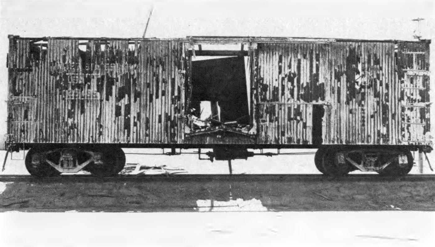
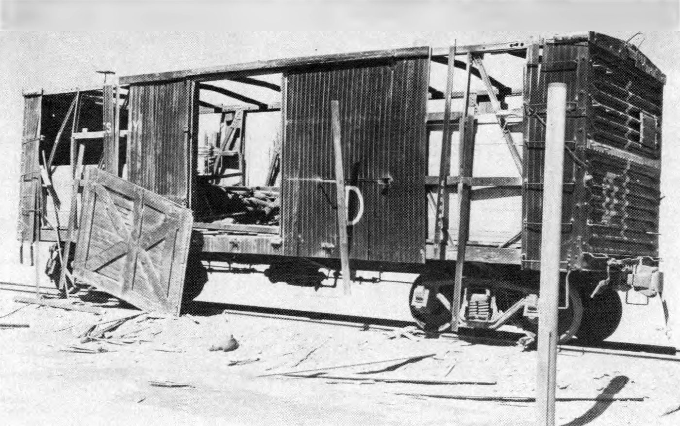
5.92 Railroad equipment suffered blast damage in Japan and also in tests in Nevada. Like motor vehicles, these targets are primarily drag sensitive and damage cannot be directly related to overpressure. At a peak overpressure of 2 pounds per square inch from a kiloton-range weapon, an empty wooden boxcar may be expected to receive relatively minor damage. At 4 pounds per square inch overpressure, the damage to a loaded wooden boxcar would be more severe (Fig. 5.92a). At a peak overpressure of 6 pounds per square inch the body of an empty wooden boxcar, weighing about 20 tons, was lifted off the trucks, i.e., the wheels, axles, etc., carrying the body, and landed about 6 feet away. The trucks themselves were pulled off the rails, apparently by the brake rods connecting them to the car body. A similar boxcar, at the same location, loaded with 30 tons of sandbags remained upright (Fig. 5.92b). Although the sides were badly damaged and the roof demolished, the car was capable of being moved on its own wheels. At 7.5 pounds per square inch peak overpressure, a loaded boxcar of the same type was overturned, and at 9 pounds per square inch it was completely demolished.
5.93 A Diesel locomotive weighing 46 tons was exposed to a peak overpressure of 6 pounds per square inch while the engine was running. It continued to operate normally after the blast, in spite of damage to windows and compartment doors and panels. There was no damage to the railroad track at this point.
AIRCRAFT
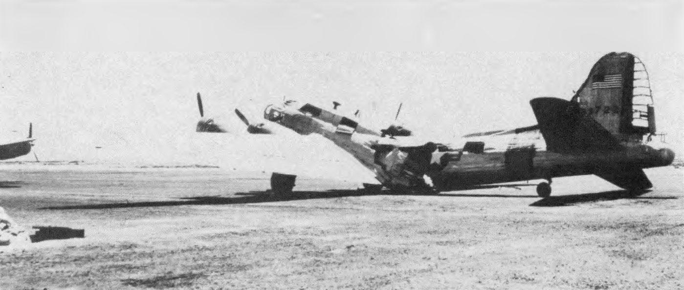
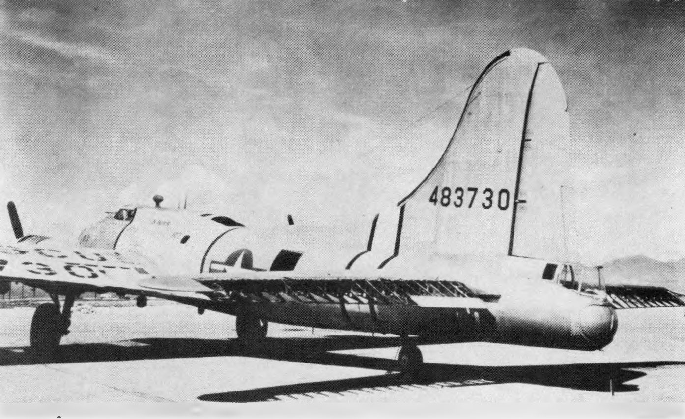
5.94 Aircraft are damaged by blast effects at levels of peak overpressure as low as 1 to 2 pounds per square inch. Complete destruction or damage beyond economical repair may be expected at peak overpressures of 4 to 10 pounds per square inch. Within this range, the peak overpressure appears to be the main criterion of damage. However, tests indicate that, at a given overpressure, damage to an aircraft oriented with the nose toward the burst will be less than damage to one with the tail or a side directed toward the explosion.
5.95 Damage to an aircraft exposed with its left side to the blast at a peak overpressure of 3.6 pounds per square inch is shown in Fig. 5.95a. The fuselage of this aircraft failed completely just ah of the wing. The skin of the fuselage, stabilizers, and engine cowling was severely buckled. Figure 5.95b shows damage to an aircraft oriented with its tail toward the burst and exposed to 2.4 pounds per square inch peak overpressure. Skin was dished in on the vertical stabilizer, horizontal stabilizers, wing surface above the flaps, and outboard wing sections. Vertical stabilizer bulkheads and the fuselage frame near the cockpit were buckled.
SHIPPING
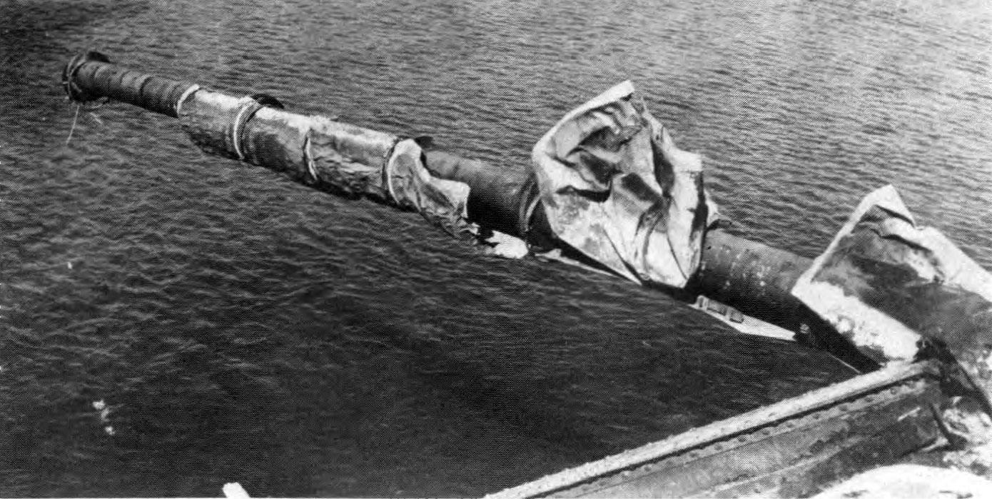
5.96 Damage to ships from an air or surface burst is due primarily to the air blast, since little pressure is transmitted through the water. At closer ranges, air blast can cause hull rupture resulting in flooding and sinking. Such rupture appears likely to begin near the waterline on the side facing the burst. Since the main hull generally is stronger than the superstructure, structures and equipment exposed above the waterline may be damaged at ranges well beyond that at which hull rupture might occur. Masts, spars, radar antennas, stacks, electrical equipment, and other light objects are especially sensitive to air blast. Damage to masts and stacks is apparent in Fig. 5.96; the ship was approximately 0.47 mile from surface zero at the ABLE test (about 20-kiloton air burst) at Bikini in 1946. Air blast may also roll and possibly capsize the ship; this effect would be most pronounced for the air blast wave from a large weapon striking the ship broadside.

5.97 Blast pressures penetrating through openings of ventilation systems and stack-uptake systems can cause damage to interior equipment and compartments, and also to boilers. Damage to the latter may result in immobilization of the ship. The distortion of weather bulkheads may render useless interior equipment mounted on or near them. Similarly, the suddenly applied blast loading induces rapid motion of the structures which may cause shock damage to interior equipment. Equipment in the superstructure is most susceptible to this type of damage, although shock motions may be felt throughout the ship.
UTILITIES
ELECTRICAL DISTRIBUTION SYSTEMS
5.98 Because of the extensive damage caused by the nuclear explosions to the cities in Japan, the electrical distribution systems suffered severely. Utility poles were destroyed by blast or fire, and overhead lines were heavily damaged at distances up to 9,000 feet (1.7 miles) from ground zero (Fig. 5.98). Underground electrical circuits were, however, little affected. Switchgear and transformers were not damaged so much directly by blast as by secondary effects, such as collapse of the structure in which they were located or by debris. Motors and generators were damaged by fire.
5.99 A fairly extensive study of the effects of a nuclear explosion on electric utilities was made in the Nevada tests in 1955. Among the purposes of these tests were the following: (1) to determine the blast pressure at which standard electrical equipment might be expected to suffer little or no damage; (2) to study the extent and character of the damage that might be sustained in a nuclear attack; and (3) to determine the nature of the repairs that would be needed to restore electrical service in those areas where homes and factories would survive sufficiently to permit their use after some repair. With these objectives in mind, two identical power systems were erected; one to be subjected to a peak overpressure of about 5 and a dynamic pressure of 0.6 pounds per square inch and the other to 1.7 and 0.1 pounds per square inch, respectively. It will be recalled that, at the lower overpressure, typical American residences would not be damaged beyond the possibility of further use.
5.100 Each power system consisted of a high-voltage (69-kV) transmission line on steel towers connected to a conventional, outdoor transformer substation. From this proceeded typical overhead distribution lines on 15 wood poles; the latter were each 45 feet long and were set 6 feet in the ground. Service drops from the overhead lines supplied electricity to equipment placed in some of the houses used in the tests described earlier. These installations were typical of those serving an urban community. In addition, the 69-kV transmission line, the 69-kV switch rack with oil circuit-breakers, and power transformer represented equipment of the kind that might supply electricity to large industrial plants.
5.101 At a peak overpressure of 5 and a dynamic pressure of 0.6 pounds per square inch the power system suffered to some extent, but it was not seriously harmed. The type of damage appeared, on the whole, to be similar to that caused by severe wind storms. In addition to the direct effect of blast, some destruction was due to missiles.
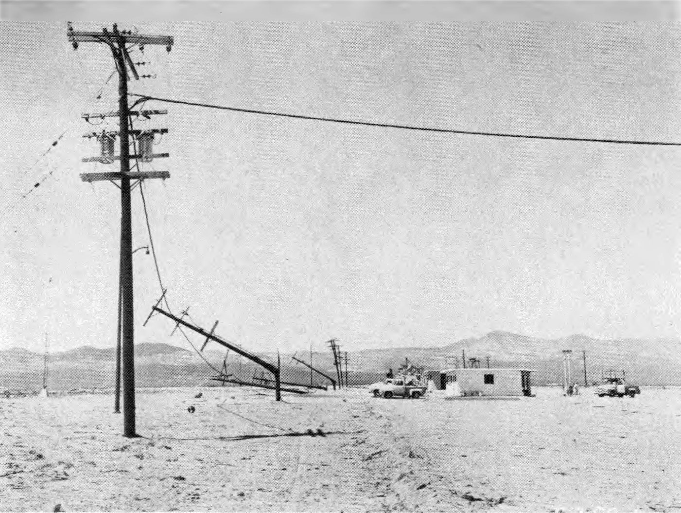
5.102 The only damage suffered by the high-voltage transmission line was the collapse of the suspension tower, bringing down the distribution line with it (Fig. 5.102a). It may be noted that the dead-end tower, which was much stronger and heavier, and another suspension tower of somewhat stronger design were only slightly affected (Fig. 5.102b). In some parts of the United States, the suspension towers are of similar heavy construction. Structures of this type are sensitive to drag forces which are related to dynamic pressure and positive phase duration, so that the overpressure is not the important criterion of damage.

5.103 The transformer substation survived the blast with relatively minor damage to the essential components. The metal cubicle, which housed the meters, batteries, and relays, suffered badly, but this substation and its contents were not essential to the emergency operation of the power system. The 4-kV regulators had been shifted on the concrete pad, resulting in separation of the electrical connections to the bus. The glass cells of the batteries were broken and most of the plates were beyond repair. But relays, meters, and other instruments were undamaged, except for broken glass. The substation as a whole was in sufficiently sound condition to permit operation on a nonautomatic (manual) basis. By replacing the batteries, automatic operation could have been restored.
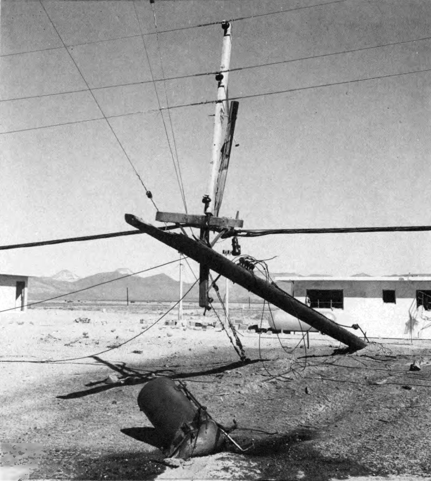
5.104 Of the 15 wood poles used to carry the lines from the substation to the houses, four were blown down completely and broken, and two others were extensively damaged. The collapse of the poles was attributed partly to the weight and resistance of the aerial cable (Fig. 5.104). Other damage was believed to be caused by missiles.
5.105 Several distributor transformers had fallen from the poles and secondary wires and service drops were down (Fig. 5.105). Nevertheless the transformers, pot heads, arresters, cutouts, primary conductors of both aluminum and copper, and the aerial cables were unharmed. Although the pole line would have required some rebuilding, the general damage was such that it could have been repaired within a day or so with materials normally carried in stock by electric utility companies.
GAS, WATER, AND SEWERAGE SYSTEMS
5.106 The public utility system in Nagasaki was similar to that of a somewhat smaller town in the United States, except that open sewers were used. The most significant damage was suffered by the water supply system, so that it became almost impossible to extinguish fires. Except for a special case, described below, loss of water pressure resulted from breakage of pipes inside and at entrances to buildings or on structures, rather than from the disruption of underground mains (Figs. 5.106a and b). The exceptional case was one in which the 12-inch cast iron water pipes were 3 feet below grade in a filled-in area. A number of depressions, up to 1 foot in depth, were produced in the fill, and these caused failure of the underground pipes, presumably due to unequal displacements.

5.107 There was no appreciable damage to reservoirs and water-treatment plants in Japan. As is generally the case, these were located outside the cities, and so were at too great a distance from the explosions to be damaged in any way.
5.108 Gas holders suffered heavily from blast up to 6,000 feet (1.1 miles) from ground zero and the escaping gas was ignited, but there was no explosion. Underground gas mains appear to have been little affected by the blast.
NATURAL AND MANUFACTURED GAS INSTALLATIONS
5.109 One of the objectives of the tests made in Nevada m 1955 was to determine the extent to which natural and manufactured gas utility installations might be disrupted by a nuclear explosion. The test was intended, in particular, to provide information concerning the effect of blast on critical underground units of a typical gas distribution system.
5.110 The installations tested were of two kinds, each in duplicate. The first represented a typical underground gas-transmission and distribution main of 6-inch steel and cast iron pipe, at a depth of 3 feet, with its associated service pipes and attachments. Valve pits of either brick or concrete blocks contained 6-inch valves with piping and protective casings. A street regulator vault held a 6-inch, low-pressure, pilot-loaded regulator, attached to steel piping projecting through the walls. One of these underground systems was installed where the blast overpressure was about 30 pounds per square inch and the other at 5 pounds per square inch. No domestic or ordinary industrial structures at the surface would have survived the higher of these pressures.
5.111 The second type of installation consisted of typical service lines of steel, copper, and plastic materials connected to 20-foot lengths of 6-inch steel main. Each service pipe rose out of the ground at the side of a house, and was joined to a pressure regulator and meter. The pipe then entered the wall of the house about 2 feet above floor level. The copper and plastic services terminated inside the wall, so that they would be subject to strain if the house moved on its foundation. The steel service line similarly terminated inside the wall, but it was also attached outside to piping that ran around the back of the house at ground level to connect to the house piping. This latter connection was made with flexible seamless bronze tubing, passing through a sleeve in the wall of the building. Typical domestic gas appliances, some attached to the interior piping, were located in several houses. Duplicate installations were located at peak overpressures of 5 and 1.7 pounds per square inch, respectively.
5.112 Neither of the underground installations was greatly affected by the blast. At the 30 pounds per square inch peak overpressure location a 1 1/2-inch pipe pressure-test riser was bent to the ground, and the valve handle, stem, and bonnet had blown off. At the same place two 4-inch ventilating pipes of the street regulator-vaults were sheared off just below ground level. A few minor leaks developed in jute and lead caulked cast iron bell and spigot joints because of ground motion, presumably due to ground shock induced by air blast. Otherwise the blast effects were negligible.
5.113 At the peak overpressure of 1.7 pounds per square inch, where the houses did not suffer severe damage, (§ 5.59), the service piping both inside and outside the houses was unharmed, as also were pressure regulators and meters. In the two-story, brick house at 5 pounds per square inch peak overpressure, which was demolished beyond repair (§ 5.57), the piping in the basement was displaced and bent as a result of the collapse of the first floor. The meter also became detached from the fittings and fell to the ground, but the meter itself and the regulator were undamaged and still operable. All other service piping and equipment were essentially intact.
5.114 Domestic gas appliances, such as refrigerators, ranges, room heaters, clothes dryers, and water heaters suffered to a moderate extent only. There was some displacement of the appliances and connections which was related to the damage suffered by the house. However, even in the collapsed two-story, brick house (§ 5.67), the upset refrigerator and range were probably still usable, although largely buried in debris. The general conclusion is, therefore, that domestic gas (and also electric) appliances would be operable in all houses that did not suffer major structural damage.
LIQUID PETROLEUM (LP) GAS INSTALLATIONS
5.115 Various LP-gas installations have been exposed to air blast from nuclear tests in Nevada to determine the effects of typical gas containers and supply systems such as are found at suburban and farm homes and at storage, industrial, and utility plants. In addition, it was of interest to see what reliance might be placed upon LP-gas as an emergency fuel after a nuclear attack.
5.116 Two kinds of typical home (or small commercial) LP-gas installations were tested: (1) a system consisting of two replaceable ICC-approved cylinders each of 100-pound capacity; and (2) a 500-gallon bulk storage type system filled from a tank truck. Some of these installations were in the open and others were attached, in the usual manner, by means of either copper tubing or steel pipe service line, to the houses exposed to peak overpressures of 5 and 1.7 pounds per square inch. Others were located where the peak overpressures were about 25 and 10 pounds per square inch. In these cases, piping from the gas containers passed through a concrete wall simulating the wall of a house.
5.117 In addition to the foregoing, a complete bulk storage plant was erected at a point where the peak overpressure was 5 pounds per square inch. This consisted of an 18,000-gallon tank (containing 15,400 gallons of propane), pump compressor, cylinder-filling building, cylinder dock, and all necessary valves, fittings, hose, accessories, and interconnecting piping.
5.118 The dual-cylinder installation, exposed to 25 pounds per square inch peak overpressure, suffered most; the regulators were torn loose from their mountings and the cylinders displaced. One cylinder came to rest about 2,000 feet from its original position; it was badly dented, but was still usable. At both 25 and 10 pounds per square inch peak overpressure the components, although often separated, could generally be salvaged and used again. The cylinder installations at 5 pounds per square inch peak overpressure were mostly damaged by missiles and falling debris from the houses to which they were attached. The component parts, except for the copper tubing, suffered little and were usable. At 1.7 pounds per square inch, there was neither damage to nor dislocation of LP-gas cylinders. Of those tested, only one cylinder developed a leak, and this was a small puncture resulting from impact with a sharp object.
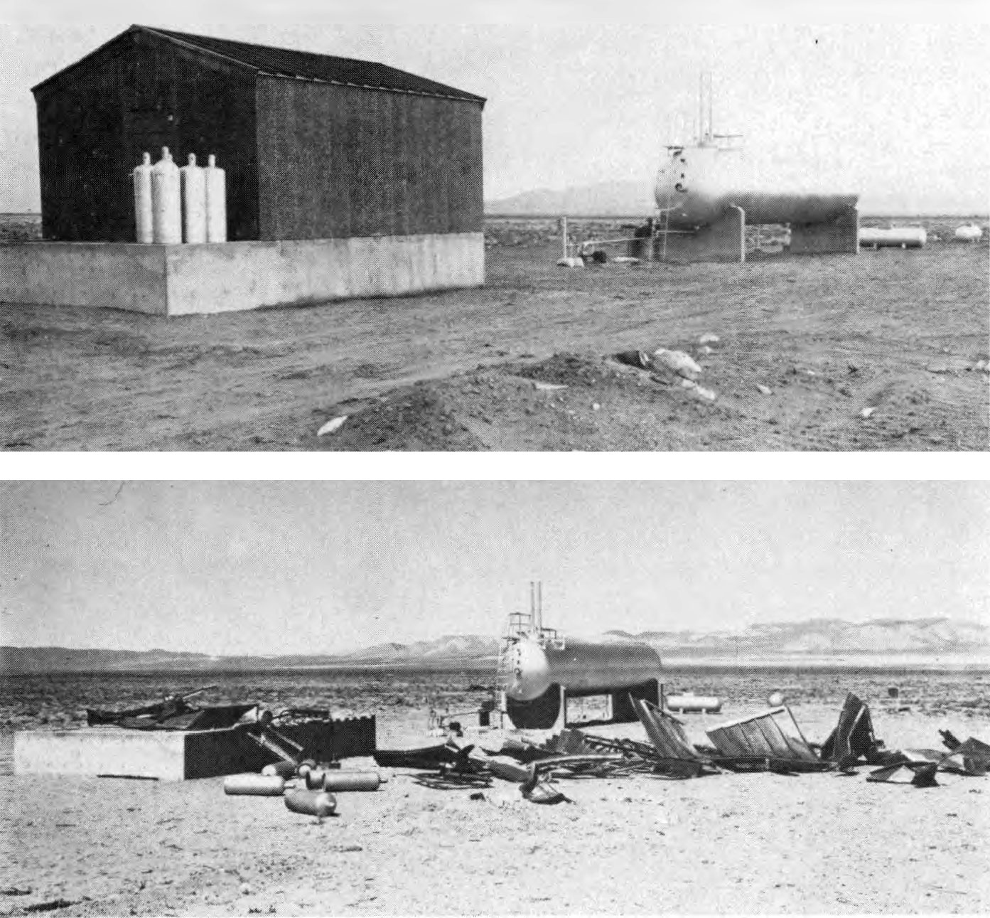
5.119 The 500-gallon bulk gas tanks also proved very durable and experienced little damage. The tank closest to the explosion was bounced end over-end for a distance of some 700 feet; nevertheless, it suffered only superficially and its strength and serviceability were not impaired. The filler valve was damaged, but the internal check valve prevented escape of the contents. The tank exposed at 10 pounds per square inch peak overpressure was moved about 5 feet, but it sustained little or no damage. All the other tanks, at 5 or 1.7 pounds per square inch, including those at houses piped for service, were unmoved and undamaged (Fig. 5.73).
5.120 The equipment of the 18,000-gallon bulk storage and filling plant received only superficial damage from the blast at 5 pounds per square inch peak overpressure. The cylinder-filling building was completely demolished; the scale used for weighing the cylinders was wrecked, and a filling line was broken at the point where it entered the building (Fig. 5.120). The major operating services of the plant would, however, not be affected because the transfer facilities were outside and undamaged. All valves and nearly all piping in the plant were intact and there was no leakage of gas. The plant could have been readily put back into operation if power, from electricity or a gasoline engine, were restored. If not, liquid propane in the storage tank could have been made available by taking advantage of gravity flow in conjunction with the inherent pressure of the gas in the tank.
5.121 The general conclusion to be drawn from the tests is that standard LP-gas equipment is very rugged, except for copper tubing connections. Disruption of the service as a result of a nuclear attack would probably be localized and perhaps negligible, so that LP-gas might prove to be a very useful emergency fuel. Where LP-gas is used mainly for domestic purposes, it appears that the gas supply would not be affected under such conditions that the house remains habitable.
MISCELLANEOUS TARGETS
COMMUNICATIONS EQUIPMENT
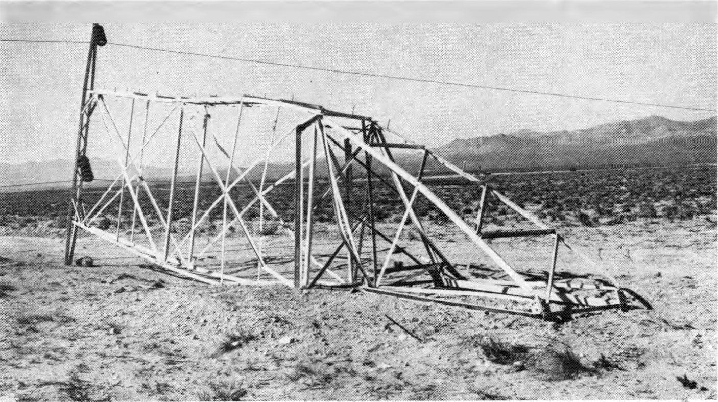
5.122 The importance of having communications equipment in operating condition after a nuclear attack is evident and so a variety of such equipment has been tested in Nevada. Among the items exposed to air blast were mobile radio-communication systems and units, a standard broadcasting transmitter, antenna towers, home radio and television receivers, telephone equipment (including a small telephone exchange), public address sound systems, and sirens. Some of these were located where the peak overpressure was 5 pounds per square inch, and in most cases there were duplicates at 1.7 pounds per square inch. The damage at the latter location was of such a minor character that it need not be considered here.
5.123 At the higher overpressure region, where typical houses were damaged beyond repair, the communications equipment proved to be very resistant to blast. This equipment is drag sensitive and so the peak overpressure does not determine the extent of damage. Standard broadcast and television receivers, and mobile radio base stations were found to be in working condition, even though they were covered with debris and had, in some cases, been damaged by missiles, or by being thrown or dropped several feet. No vacuum or picture tubes were broken. The only mobile radio station to be seriously affected was one in an automobile which was completely crushed by a falling chimney.
5.124 A guyed 150-foot antenna tower was unharmed, but an unguyed 120-foot tower, of lighter construction, close by, broke off at a height of about 40 feet and fell to the ground (Fig. 5.124). This represented the only serious damage to any of the equipment tested.

5.125 The base station antennas, which were on the towers, appeared to withstand blast reasonably well, although those attached to the unguyed tower, referred to above, suffered when the tower collapsed. As would have been expected from their lighter construction, television antennas for home receivers were more easily damaged. Several were bent both by the blast and the collapse of the houses upon which they were mounted. Since the houses were generally damaged beyond repair at a peak overpressure of 5 pounds per square inch, the failure of the television antennas is not of great significance.
5.126 Some items, such as power lines and telephone service equipment, were frequently attached to utility-line poles. When the poles failed, as they did in some cases (§ 5.104), the communications systems suffered accordingly. Although the equipment operated satisfactorily after repairs were made to the wire line, it appears that the power supply represents a weak link in the communications chain.
BRIDGES
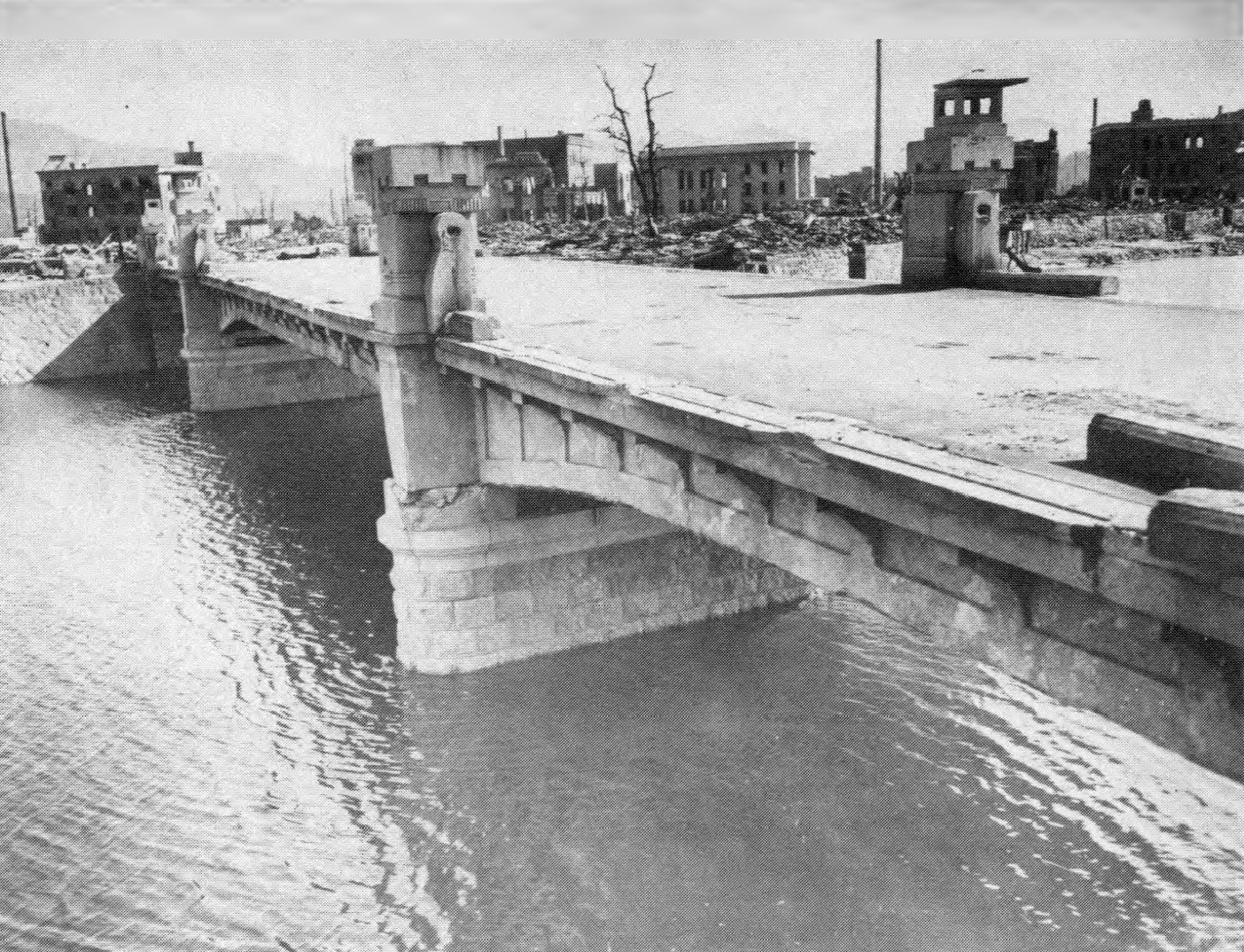
5.127 There were a number of different kinds of bridges exposed to the nuclear explosions in Hiroshima and Nagasaki. Those of wood were burned in most cases, but steel-girder bridges suffered relatively little destruction (Figs. 5.127a and b). One bridge, only 270 feet from ground zero, i.e., about 2,100 feet from the burst point, which was of a girder type with a reinforced concrete deck, showed no sign of any structural damage. It had, apparently, been deflected downward by the blast force and had rebounded, causing only a slight net displacement. Other bridges, at greater distances from ground zero, suffered more lateral shifting. A reinforced-concrete deck was lifted from the supporting steel girder of one bridge, apparently as a result of reflection of the blast wave from the surface of the water below.

HEAVY-DUTY MACHINE TOOLS
5.128 The vulnerability of heavy duty machine tools and their components to air blast from a nuclear explosion was studied at the Nevada Test Site to supplement the information from Nagasaki (§ 5.33). A number of machine tools were anchored on a reinforced-concrete slab in such a manner as to duplicate good industrial practice. Two engine lathes (weighing approximately 7,000 and 12,000 pounds, respectively), and two horizontal milling machines (7,000 and 10,000 pounds, respectively) were exposed to a peak overpressure of 10 pounds per square inch. A concrete-block wall, 8 inches thick and 64 inches high, was constructed immediately in front of the machines, i.e., between the machines and ground zero (Fig. 5.128). The purpose of this wall was to simulate the exterior wall of the average industrial plant and to provide debris and missiles.

5.129 Of the four machines, the three lighter ones were moved from their foundations and damaged quite badly (Fig. 5.129a). The fourth, weighing 12,000 pounds, which was considered as the only one to be actually of the heavy-duty type, survived (Fig. 5.129b). From the observations it was concluded that a properly anchored machine tool of the true heavy-duty type would be able to withstand peak overpressures of 10 pounds per square inch or more without substantial damage.

5.130 In addition to the direct effects of blast, considerable destruction was caused by debris and missiles, much of which resulted from the expected complete demolition of the concrete-block wall. Delicate mechanisms and appendages, which are usually on the exterior and unprotected, suffered especially severely. Gears and gear cases were damaged, hand valves and control levers were broken off, and drive belts were broken. It appears, however, that most of the missile damage could be easily repaired if replacement parts were available, since major dismantling would not be required.
5.131 Behind the two-story brick house in the peak overpressure region of 5 pounds per square inch (§ 5.67), a 200-ton capacity hydraulic press weighing some 49,000 pounds was erected. The location was chosen as being the best to simulate actual factory conditions. This unusually tall (19 feet high) and slim piece of equipment showed little evidence of blast damage, even though the brick house was demolished. It was probable that the house provided some shielding from the blast wave. Moreover, at the existing blast pressure, missiles did not have high velocities. Such minor damage as was suffered by the machine was probably due to debris falling from the house.
5.132 At the 3-pounds per square inch peak overpressure location, there were two light, industrial buildings of standard type. In each of these was placed a vertical milling machine weighing about 3,000 pounds, a 50-gallon capacity, stainless-steel, pressure vessel weighing roughly 4,100 pounds, and a steel steam oven approximately 2½ feet wide, 5 feet high, and 9 feet long. Both buildings suffered extensively from blast, but the equipment experienced little or no operational damage. In one case, the collapsing structure fell on and broke off an exposed part of the milling machine.
5.133 The damage sustained by machine tools in the Nevada tests was probably less than that suffered in Japan at the same blast pressures (§ 5.33). Certain destructive factors, present in the latter case, were absent in the tests. First, the conditions were such that there was no damage by fire; and, second, there was no exposure to the elements after the explosion. In addition, the total amount of debris and missiles produced in the tests was probably less than in the industrial buildings in Japan.
ANALYSIS OF DAMAGE FROM AIR BLAST
INTRODUCTION
5.134 The remainder of this chapter is concerned with descriptions of air-blast damage criteria for various types of targets and with the development of damage-distance relationships for predicting the distances at which damage may be expected from nuclear explosions of different energy yields. The nature of any target complex, such as a city, is such, however, that exact predictions are not possible. Nevertheless, by application of proper judgment to the available information, results of practical value can be obtained. The conclusions given here are considered to be applicable to average situations that might be encountered in an actual target complex.
5.135 Damage to structures and objects is generally classified in three categories: severe, moderate, and light. In several of the cases discussed below, the specific nature of each type of damage is described, but the following broad definitions are a useful guide.
- Severe Damage
- A degree of damage that precludes further use of the structure or object for its intended purpose without essentially complete reconstruction. For a structure or building, collapse is generally implied.
- Moderate Damage
- A degree of damage to principal members that precludes effective use of the structure or object for its intended purpose unless major repairs are made.
- Light Damage
- A degree of damage to buildings resulting in broken windows, slight damage to roofing and siding, blowing down of light interior partitions, and slight cracking of curtain walls in buildings. Minor repairs are sufficient to permit use of the structure or object for its intended purpose.
5.136 For a number of types of targets, the distances out to which different degrees of damage may be expected from nuclear explosions of various yields have been represented by diagrams, such as Figs. 5.140 and 5.146. These are based on observations made in Japan and at various nuclear tests, on experiments conducted in shock tubes in laboratories and with high-explosives in field tests, and on theoretical analyses of the loading and response of structures (see Chapter IV). As a result of these studies, it is possible to make reasonably accurate predictions of the response of interior as well as exterior wall panels and complete structures to the air-blast wave. These predictions, however, must take into account constructional details of each individual structure. Moreover, observations made during laboratory tests have indicated a large scatter in failure loadings as a result of statistical variations among wall and material properties. The data in Figs. 5.140 and 5.146 are intended, however, to provide only gross estimates for the categories of structures given in Tables 5.139a and b. The response of a particular structure may thus deviate from that shown for its class in the figures.
5.137 For structures that are damaged primarily by diffraction loading (§ 4.03), the peak overpressure is the important factor in determining the response to blast. In some instances, where detailed analyses have not been performed, peak overpressures are given for various kinds of damage. Approximate damage-distance relationships can then be derived by using peak overpressure-distance curves and scaling laws from Chapter III. For equal scaled heights of burst, as defined in § 3.62, the range for a specified damage to a diffraction-sensitive structure increases in proportion to the cube root, and the damage area in proportion to the two-thirds power, of the energy of the explosion. This means, for example, that a thousand-fold increase in the energy will increase the range for a particular kind of diffraction-type damage by a factor of roughly ten; the area over which the damage occurs will be increased by a factor of about a hundred, for a given scaled burst height.
5.138 Where the response depends mainly on drag (or wind) loading, the peak overpressure is no longer a useful criterion of damage. The response of a drag-sensitive structure is determined by the length of the blast wave positive phase as well as by the peak dynamic pressure (§ 4.12 et seq.). The greater the energy of the weapon, the farther will be the distance from the explosion at which the peak dynamic pressure has a specific value and the longer will be the duration of the positive phase. Since there is increased drag damage with increased duration at a given pressure, the same damage will extend to lower dynamic pressure levels. Structures which are sensitive to drag loading will therefore be damaged over a range that is larger than is given by the cube root rule for diffraction-type structures. In other words, as the result of a thousand-fold increase in the energy of the explosion, the range for a specified damage to a drag-sensitive structure will be increased by a factor of more than ten, and the area by more than a hundred.
ABOVE-GROUND BUILDINGS AND BRIDGES
5.139 The detailed nature of the damage in the severe, moderate, and light categories to above-ground structures of various types are given in Tables 5.139a and b. For convenience, the information is divided into two groups. Table 5.139a is concerned with structures of the type that are primarily affected by the blast wave during the diffraction phase, whereas the structures in Table 5.139b are drag sensitive.
| Description of Damage | ||||
|---|---|---|---|---|
| Structural Type | Description of Structure | Severe | Moderate | Light |
| 1 | Multistory reinforced concrete building with reinforced concrete walls, blast resistant design for 30 psi Mach region pressure from 1 MT, no windows. | Walls shattered, severe frame distortion, incipient collapse. | Walls breached or on the point of being so, frame distorted, entrance-ways damaged, doors blown in or jammed, extensive spalling of concrete. | Some cracking of concrete walls and frame. |
| 2 | Multistory reinforced concrete building with concrete walls, small window area, three to eight stories. | Walls shattered, severe frame distortion, incipient collapse. | Exterior walls severely cracked. Interior partitions severely cracked or blown down. Structural frame permanently distorted, extensive spalling of concrete. | Windows and doors blown in, interior partitions cracked. |
| 3 | Multistory wall-bearing building. brick apartment house type, up to three stories. | Collapse of bearing walls, resulting in total collapse of structure. | Exterior walls severely cracked, interior partitions severely cracked or blown down. | Windows and doors blown in, interior partitions cracked. |
| 4 | Multistory wall-bearing building, monumental type. up to four stories. | Collapse of bearing walls, resulting in collapse of structure supported by these walls. Some bearing walls may be shielded by intervening walls so that part of the structure may receive only moderate damage. | Exterior walls facing blast severely cracked. interior partitions severely cracked with dam- age toward far end of building possibly less intense. | Windows and doors blown in, interior partitions cracked. |
| 5 | Wood frame building, house type. one or two stories. | Frame shattered resulting in almost complete collapse. | Wall framing cracked. Roof severely damaged, interior partitions blown down. | Windows and doors blown in. interior partitions cracked. |
| Description of Damage | ||||
|---|---|---|---|---|
| Structural Type | Description of Structure | Severe | Moderate | Light |
| 6 | Light steel frame industrial building, single story, with up to 5-ton crane capacity; low strength walls which fail quickly. | Severe distortion or collapse of frame. | Minor to major distortion of frame; cranes, if any, not operable until repairs made. | Windows and doors blown in, light siding ripped off. |
| 7 | Heavy steel-frame industrial building, single story, with 25 to 50-ton crane capacity; lightweight, low strength wall which fail quickly. | Severe distortion or collapse of frame. | Some distortion to frame; cranes not operable until repairs made. | Windows and doors blown in, light siding ripped off. |
| 8 | Heavy steel frame industrial building, single story, with 60 to 100-ton crane capacity; lightweight low strength walls which fail quickly. | Severe distortion or collapse of frame. | Some distortion or frame; cranes not operable until repairs made. | Windows and doors blown in, light siding ripped off |
| 9 | Multistory steel-frame office-type building, 3 to 10 stories. Lightweight low strength walls which fail quickly, earthquake resistant construction. | Severe frame distortion, incipient collapse. | Frame distorted moderately, interior partitions blown down. | Windows and doors blown in, light siding ripped off, interior partition |
| 10 | Multistory steel-frame office-type building, 3 to 10 stories. Lightweight low strength walls which fail quickly, non-earthquake resistant construction | Severe frame distortion, incipient collapse. | Frame distorted moderately, interior partitions blown down. | Windows and doors blown in, light siding ripped off, interior partitions cracked. |
| 11 | Multistory reinforced concrete frame office-type building, 3 to 10 stories; light- weight low strength walls which fail quickly, earthquake resistant construction. | Severe frame distortion, incipient collapse. | Frame distorted moderately, interior partitions blown down, some spalling of concrete. | Windows and doors blown in, light siding ripped off, interior partitions cracked. |
| 12 | Multistory reinforced concrete frame office type building, 3 to 10 stories; lightweight low strength walls which fail quickly, non-earthquake resistant construction. | Severe frame distortion, incipient collapse | Frame distorted moderately, interior partitions blown down, some spalling of concrete. | Windows and doors blown in, light siding ripped off, interior partitions cracked. |
| 13 | Highway truss bridges, 4-lane, spans 200 to 400 ft; railroad truss bridges, double track ballast floor, spans 200 to 400 ft. | Total failure of lateral bracing or anchorage, collapse of bridge. | Substantia! distortion of lateral bracing or slippage on supports, significant reduction in capacity of bridge. | Capacity of bridge not significantly reduced, slight distortion of some bridge components. |
| 14 | Highway truss bridges, 2-lane, spans 200 to 400 ft; railroad truss bridges, single track ballast or double track open floors, spans 200 to 400 ft; railroad truss bridges, single track open floor, span 400 ft. | (Ditto) | (Ditto) | (Ditto) |
| 15 | Railroad truss bridges, single track open floor, span 200 ft. | (Ditto) | (Ditto) | (Ditto) |
| 16 | Highway girder bridges, 4-lane through, span 75 ft. | (Ditto) | (Ditto) | (Ditto) |
| 17 | Highway girder bridges, 2-lane deck, 2-lane through, 4-lane deck, span 75 ft; railroad girder bridges, double-track deck, open or ballast floor, span 75 ft; railroad girder bridges, single or double track through, ballast floors, span 75 ft. | (Ditto) | (Ditto) | (Ditto) |
| 18 | Railroad girder bridges, single track deck, open or ballast floors, span 75 ft; railroad girder bridges, single or double track through, open floors, span 75 ft | (Ditto) | (Ditto) | (Ditto) |
| 19 | Highway girder bridges, 2-lane through, 4-lane deck or through, span 200 ft; railroad girder bridges, double track deck or through, ballast floor, span 200 ft | (Ditto) | (Ditto) | (Ditto) |
| 20 | Highway girder bridges, 2-lane deck, span 200 ft; railroad girder bridges, single track deck or through, ballast floors, span 200 ft; railroad girder bridges, double track deck or through, open floors, span 200 ft. | (Ditto) | (Ditto) | (Ditto) |
| 21 | Railroad girder bridges, single track deck or through, open floors, span 200 ft. | (Ditto) | (Ditto) | (Ditto) |
5.140 The ranges for severe and moderate damage to the structures in Tables 5.139a and b are presented in Fig. 5.140, based on actual observations and theoretical analysis. The numbers (I to 21) in the figure identify the target types as given in the first column of the tables. The data refer to air bursts with the height of burst chosen so as to maximize the radius of damage for the particular target being considered and is not necessarily the same for different targets. For a surface burst, the respective ranges are to be multiplied by three-fourths. An example illustrating the use of the diagram is given.

5.141 The data in Fig. 5.140 are for certain average target conditions. These are that (I) the target is at sea level (no correction is necessary if the target altitude is less than 5,000 feet); (2) the terrain is fairly flat (rugged terrain would provide some local shielding and protection in certain areas and local enhancement of damage in others); and (3) the structures have average characteristics (that is, they are of average size and strength and that orientation of the target with respect to the burst is no problem, i.e., that the ratio of loading to resistance is relatively the same in all directions from the target).
5.142 The “fan” from each point in the figure designating a target type delineates the range of yields over which theoretical analyses have been made. For yields falling within this range, the diagram is estimated to be accurate within ± 20 percent for the average conditions discussed above. The significance of results obtained by applying the diagram to conditions that depart appreciably from the average or to yields outside the limits of the fans must be left to the judgment of the analyst.
5.143 Figure 5.140 gives the distances from ground zero for severe and moderate damage. Light damage to all targets except blast-resistant structures and bridges can be expected at the range at which the overpressure is 1 pound per square inch. For the blast-resistant structure (Type 1) described in Table 5.139a, a peak overpressure of 10 pounds per square inch should be used to estimate the distance for light damage. Light damage to bridges can be expected at the range at which 0.6 pound per square inch dynamic pressure occurs.
5.144 The foregoing results do not take into consideration the possibility of fire. Generally speaking, the direct effects of thermal radiation on the structures and other targets under consideration are inconsequential. However, thermal radiation may initiate fires, and in structures with severe or moderate damage fires may start because of disrupted gas and electric utilities. In some cases, as in Hiroshima (§ 7.71), the individual fires may develop into a mass fire which may exist throughout a city, even beyond the range of significant blast damage. The spread of such a fire depends to a great extent on local weather and other conditions and is therefore difficult to predict. This limitation must be kept in mind when Fig. 5.140 is used to estimate the damage to a particular city or target area.
STRUCTURAL ELEMENTS
5.145 For certain structural elements, with short periods of vibration (up to about 0.05 second) and small plastic deformation at failure, the conditions for failure can be expressed as a peak overpressure without considering the duration of the blast wave. The failure conditions for elements of this type are given in Table 5.145. Some of these elements fail in a brittle fashion, and thus there is only a small difference between the pressures that cause no damage and those that produce complete failure. Other elements may fail in a moderately ductile manner, but still with little difference between the pressures for light damage and complete failure. The pressures are side-on blast overpressures for panels that face ground zero. For panels that are oriented so that there are no reflected pressures thereon, the side-on pressures must be doubled. The fraction of the area of a panel wall that contains windows will influence the overpressure required to damage the panel. Such damage is a function of the net load, which may be reduced considerably if the windows fail early. This allows the pressure to become equalized on the two sides of the wall -before panel failure occurs.
| Structural element | Failure | Approximate side-on peak overpressure (psi) |
|---|---|---|
| Glass windows, large and small | Shattering usually, occasional frame failure. | 0.5 - 1.0 |
| Corrugated asbestos siding. | Shattering | 1.0 - 2.0 |
| Corrugated steel or aluminum paneling. | Connection failure followed by buckling. | 1.0 - 2.0 |
| Brick wall panel, 8 in. or 12 in. thick (not reinforced). | Shearing and flexure failures. | 3.0 - 10.0 |
| Wood siding panels, standard house construction. | Usually failure occurs at the main connections allowing a whole panel to be blown in. | 1.0 - 2.0 |
| Concrete or cinder-block wall panels, 8 in. or 12 in. thick (not reinforced) | Shattering of the wall | 1.5 - 5.5 |
DRAG-SENSITIVE TARGETS
5.146 A diagram of damage-distance relationships for various targets which are largely affected by drag forces is given in Fig. 5.146. The conditions under which it is applicable and the limits of accuracy are similar to those in § 5.141 and § 5.142, respectively; the possibility of fire mentioned in § 5.144 must also be kept in mind. The targets (Items 1 to 13) in the figure are enumerated on the page facing Fig. 5.146 and the different types of damage are described in the following paragraphs.
Transportation Equipment
5.147 The damage criteria for various types of land transportation equipment, including civilian motor-driven vehicles and earth-moving equipment, and railroad rolling stock are given in Table 5.147a. The various types of damage to merchant shipping from air blast are described in Table 5.147b.
| Description of equipment | Damage | Nature of damage |
|---|---|---|
| Motor equipment (cars and trucks). | Severe | Gross distortion of frame, large displacements, outside appurtenances (doors and hoods) torn off, need rebuilding before use. |
| Moderate | Turned over and displaced, badly dented, frames sprung, need major repairs. | |
| Light | Glass broken, dents in body, possibly turned over, immediately usable. | |
| Railroad rolling stock (box, flat, tank, and gondola cars). | Severe | Car blown from track and badly smashed, extensive distortion, some parts usable. |
| Moderate | Doors demolished, body damaged, frame distorted, could possibly roll to repair shop. | |
| Light | Some door and body damage, car can continue inuse. | |
| Railroad locomotives (Diesel or steam). | Severe | Overturned, parts blown off, sprung and twisted, major overhaul required. |
| Moderate | Probably overturned, can be towed to repair shop after being righted, need major repairs. | |
| Light | Glass breakage and minor damage to parts, immediately usable. | |
| Construction equipment (bulldozers and graders). | Severe | Extensive distortion of frame and crushing of sheet metal, extensive damage to caterpillar tracks and wheels. |
| Moderate | Some frame distortion, overturning, track and wheel damage. | |
| Light | Slight damage to cabs and housing, glass breakage |
| Damage type | Nature of damage |
|---|---|
| Severe | The ship is either sunk, capsized, or damaged to the extent of requiring rebuilding. |
| Moderate | The ship is immobilized and requires extensive repairs, especially to shock-sensitive components or their foundations, e.g., propulsive machinery, boilers, and interior equipment. |
| Light | The ship may still be able to operate, although there will be damage to electronic, electrical, and mechanical equipment. |
Communication and Power Lines
5.148 Damage to telephone, telegraph, and utility power lines is generally either severe or light. Such damage depends on whether the poles supporting the lines are damaged or not. If the poles are blown down, damage to the lines will be severe and extensive repairs will be required. On the other hand, if the poles remain standing, the lines will suffer only light damage and will need little repair. In general, lines extending radially from ground zero are less susceptible to damage than are those running at right angles to this direction.
Forests
5.149 The detailed characteristics of the damage to forest stands resulting from a nuclear explosion will depend on a variety of conditions, e.g., deciduous or coniferous trees, degree of foliation of the trees, natural or planted stands, and favorable or unfavorable growing conditions. A general classification of forest damage, applicable in most cases, is given in Table 5.149. Trees are primarily sensitive to the drag forces from a blast wave and so it is of interest that the damage in an explosion is similar to that resulting from a strong, steady wind; the velocities of such winds that would produce comparable damage are included in the table.
| Damage type | Nature of damage | Equivalent steady wind velocity (miles per hour) |
|---|---|---|
| Severe | Up to 90 percent of trees blown down; remainder denuded of branches and leaves. (Area impassable to vehicles and very difficult on foot.) | 130-140 |
| Moderate | About 30 percent of trees blown down; remainder have some branches and leaves blown off. (Area passable to vehicles only after extensive clearing.) | 90-100 |
| Light | Only applies to deciduous forest stands. Very few trees blown down; some leaves and branches blown off. (Area passable to vehicles.) | 60-80 |
5.150 The damage-distance results derived from Fig. 5.146 apply in particular to unimproved coniferous forests which have developed under unfavorable growing conditions and to most deciduous forests in the temperate zone when foliation is present. Improved coniferous forests, with trees of uniform height and a smaller average tree density per acre, are more resistant to blast than are unimproved forests which have grown under unfavorable conditions. A forest of defoliated deciduous trees is also somewhat more blast resistant than is implied by the data in Fig. 5.146.
PARKED AIRCRAFT
5.151 Aircraft are relatively vulnerable to air blast effects associated with nuclear detonations. The forces developed by peak overpressures of 1 to 2 pounds per square inch are sufficient to dish in panels and buckle stiffeners and stringers. At higher overpressures, the drag forces due to wind (dynamic) pressure tend to rotate, translate, overturn, or lift a parked aircraft, so that damage may then result from collision with other aircraft, structures, or the ground. Aircraft are also very susceptible to damage from flying debris carried by the blast wave.
5.152 Several factors influence the degree of damage that may be expected for an aircraft of a given type at a specified range from a nuclear detonation. Aircraft that are parked with the nose pointed toward the burst will suffer less damage than those with the tail or either side directed toward the oncoming blast wave (§ 5.94). Shielding of one aircraft by another or by structures or terrain features may reduce damage, especially that caused by flying debris. Standard tie-down of aircraft, as used when high winds are expected, will also minimize the extent of damage at ranges where destruction might otherwise occur.
5.153 The various damage categories for parked transport airplanes, light liaison airplanes, and helicopters are outlined in Table 5.153 together with the approximate peak overpressures at which the damage may be expected to occur. The aircraft are considered to be parked in the open at random orientation with respect to the point of burst. The data in the table are based on tests in which aircraft were exposed to detonations with yields in the kiloton range. For megaton yields, the longer duration of the positive phase of the blast wave may result in some increase in damage over that estimated from small-yield explosions at the same overpressure level. This increase is likely to be significant at pressures producing severe damage, but will probably be less important for moderate and light damage conditions.
| Damage type | Nature of damage | Overpressure (psi) | |
|---|---|---|---|
| Severe | Major (or depot level) maintenance required to restore aircraft to operational status. | Transport airplanes | 3 |
| Light liaison craft | 2 | ||
| Helicopters | 3 | ||
| Moderate | Field maintenance required to restore aircraft to operational status. | Transport airplanes | 2 |
| Light liaison craft | 1 | ||
| Helicopters | 1.5 | ||
| Light | Flight of the aircraft not prevented, although performance maybe restricted. | Transport airplanes | 1.0 |
| Light liaison craft | 0.75 | ||
| Helicopters | 1.0 | ||
5.154 Aircraft with exposed ignitable materials may, under certain conditions, be damaged by thermal radiation at distances beyond those at which equivalent damage would result from blast effects. The vulnerability to thermal radiation may be decreased by protecting ignitable materials from exposure to direct radiation or by painting them with protective (light colored) coatings which reflect, rather than absorb, most of the thermal radiation (see Chapter VII).
POL STORAGE TANKS
5.155 The chief cause of failure of POL (petroleum, oil, lubricant) storage tanks exposed to the blast wave appears to be the lifting of the tank from its foundation. This results in plastic deformation and yielding of the joint between the side and bottom so that leakage can occur. Severe damage is regarded as that damage which is associated with loss of the contents of the tank by leakage. Furthermore, the leakage can lead to secondary effects, such as the development of fires. If failure by lifting does not occur, it is expected that there will be little, if any, loss of liquid from the tank as a consequence of sloshing. There is apparently no clearcut overall structural collapse which initially limits the usefulness of the tank. Peak overpressures required for severe damage to POL tanks of diameter D may be obtained from Figs. 5.155a and b. Figure 5.155a is applicable to nuclear explosions with energy yields from 1 to 500 kilotons and Fig. 5.155b to yields over 500 kilotons. For yields less than 1-kiloton, the peak overpressure for severe damage may be taken to be 1 pound per square inch.

LIGHTWEIGHT, EARTH COVERED AND BURIED STRUCTURES
5.156 Air blast is the controlling factor for damage to lightweight earth covered structures and shallow buried underground structures. The earth cover provides surface structures with substantial protection against air blast and also some protection against flying debris. The depth of earth cover above the structure would usually be determined by the degree of protection from nuclear radiation required at the design overpressure or dynamic pressure (see Chapter VIII).
5.157 The usual method of providing earth cover for surface or “cut-and cover” semi-buried structures is to build an earth mound over the portion of the structure that is above the normal ground level. If the slope of the earth cover is chosen properly, the blast reflection factor is reduced and the aerodynamic shape of the structure is improved. This results in a considerable reduction in the applied translational forces. An additional benefit of the earth cover is the stiffening or resistance to deformation that the earth provides to flexible structures by the buttressing action of the soil.
5.158 For lightweight, shallow buried underground structures the top of the earth cover is at least flush with the original grade but the depth of cover is not more than 6 percent of the span. Such structures are not sufficiently deep for the ratio of the depth of burial to the span to be large enough to obtain the benefits described in § 5.161. The soil provides little attenuation of the air blast pressure applied to the top surface of a shallow buried underground structure. Observations made at full-scale nuclear tests indicate that there is apparently no increase in pressure on the structure as a result of ground shock reflection at the interface between the earth and the top of the structure.
5.159 The lateral blast pressures exerted on the vertical faces of a shallow buried structure have been found to be as low as 15 percent of the blast pressure on the roof in dry, well-compacted, silty soils. For most soils, however, this lateral blast pressure is likely to be somewhat higher and may approach 100 percent of the roof blast pressure in porous saturated soil. The pressures on the bottom of a buried structure, in which the bottom slab is a structural unit integral with the walls, may range from 75 to 100 percent of the pressure exerted on the roof.
5.160 The damage that might be suffered by a shallow buried structure will depend on a number of variables, including the structural characteristics, the nature of the soil, the depth of burial, and the downward pressure, i.e., the peak overpressure and direction of the blast wave. In Table 5.160 are given the limiting values of the peak overpressure required to cause various degrees of damage to two types of shallow buried structures. The range of pressures is intended to allow for differences in structural design, soil conditions, shape of earth mound, and orientation with respect to the blast wave.
| Type of structure | Damage type | Peak overpressure (psi) | Nature of damage |
|---|---|---|---|
| Light, corrugated steel arch, surface structure (10-gage corrugated steel with a span of 20—25 ft), central angle of 1800; 5 ft of earth cover at the crown.* | Severe | 45- 60 | Collapse |
| Moderate | 50- 50 | Large deformations of end walls and arch, also major entrance door damage. | |
| Light | 30- 40 | Damage to ventilation and entrance door. | |
| Buried concrete arch 8-in. thick with a 16 ft span and central angle of 1800; 4 ft of earth cover at the crown. | Severe | 220-280 | Collapse |
| Moderate | 100-220 | Large deformations with considerable cracking and spalling. | |
| Light | 120-160 | Cracking of panels, possible entrance door damage. |
5.161 Underground structures, buried at such a depth that the ratio of the burial depth to the span approaches (or exceeds) a value of 3.0, will obtain some benefit from the attenuation with depth of the pressure induced by air blast, and from the arching of the load from more deformable areas to less deformable ones. Limited experience at nuclear tests suggests that the arching action of the soil effectively reduces the loading on flexible structures.
BIBLIOGRAPHY
- , “Engineering Vibrations,” McGraw-Hill Book Co., Inc., 1958.
- * , “Damage to Commercial and Industrial Buildings Exposed to Nuclear Effects,” Federal Civil Defense Administration, February 1956, WT–1189.
- * , “Nuclear Explosion Effects on Structures and Protective Construction—A Selected Bibliography,” U.S. Atomic Energy Commission, April 1961, TID–3092.
- , “An Engineering Approach to Blast Resistant Design,” Trans. Amer. Soc. of Civil Engineers, 121, 45 (1956).
- , et al., “Structural Design for Dynamic Loads,” McGraw-Hill Book Co., Inc., 1959.
- , “Probabilistic Air Blast Failure Criteria for Urban Structures,” Stanford Research Institute, Menlo Park, California, November 1971.
- * , “Damage to Conventional and Special Types of Residences Exposed to Nuclear Effects,” OCDM, FHA, and HHFA, March 1961, WT–1194.
- , “Dynamics of Framed Structures,” John Wiley and Sons, Inc., 1959.
- * , “Exposure of Mobile Homes and Emergency Vehicles to Nuclear Explosions,” Federal Civil Defense Administration, July 1957, WT–1181.
- * , “Nuclear Effects on Machine Tools,” U.S. Atomic Energy Commission, December 1956, WT–I 184.
- * , “Blast Effects of Atomic Weapons Upon Curtain Walls and Partitions of Masonry and Other Materials,” Federal Civil Defense Administration, August 1956, WT–741.
- * , “Effects of a Nuclear Explosion on Typical Liquefied Petroleum Gas (LP–Gas) Installations and Facilities,” Liquefied Petroleum Gas Association, December 1956, WT–1175.
- , “A Review of Numerical Integration Methods for Dynamic Response of Structures,” University of Illinois Structural Research Series No. 69, 1954.
- , “Effects of a Nuclear Explosion on Commercial Communications Equipment,” Federal Civil Defense Administration, May 1955, ITR–1193.
- , et al., “A Study of Loading, Structural Response, and Debris Characteristics of Wall Panels,” URS Research Co., Burlingame, California, July 1969.
- , et al., “Final Report Summary, Structural Response and Loading of Wall Panels,” URS Research Co., Burlingame, California, July 1971.
* These documents may be purchased from the National Technical Information Service, U.S. Department of Commerce, Springfield, Virginia 22161.